Toyota Avalon (XX50): Grille Shutter Communication Stop Mode. Headlight ECU LH Communication Stop Mode. Headlight ECU RH Communication Stop Mode
Grille Shutter Communication Stop Mode
DESCRIPTION
|
Detection Item | Symptom |
Trouble Area |
| Grille Shutter Communication Stop Mode |
Any of the following conditions are met:
- Communication stop for "Grill Shutter" is indicated on the "Communication Bus Check" screen of the Techstream.
Click here 
- Communication stop history for "Grill Shutter" is indicated on the
"Communication Bus Check (Detail)" screen of the Techstream. (The Lost
Communication Time value for "Grill Shutter" is 6 or more.)
Click here
- Communication system DTCs (DTCs that start with U) that correspond to
"Grille Shutter Communication Stop Mode" in "DTC Combination Table" are
output.
Click here
|
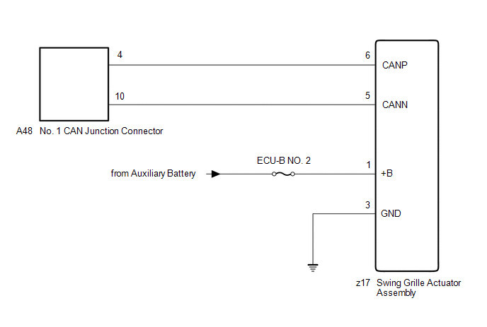
- Swing grille actuator assembly branch line or connector
- Power source circuit of swing grille actuator assembly
- Swing grille actuator assembly ground circuit
- Swing grille actuator assembly
|
WIRING DIAGRAM
CAUTION / NOTICE / HINT
CAUTION:
When performing the confirmation driving pattern, obey all speed limits and traffic laws.
NOTICE:
HINT:
- Before disconnecting related connectors for inspection, push in on each
connector body to check that the connector is not loose or disconnected.
- When a connector is disconnected, check that the terminals and connector body are not cracked, deformed or corroded.
PROCEDURE
|
1. | CHECK FOR OPEN IN CAN BUS LINES (SWING GRILLE ACTUATOR ASSEMBLY BRANCH LINE) |
(a) Disconnect the cable from the negative (-) auxiliary battery terminal.
(b) Disconnect the z17 swing grille actuator assembly connector.
| (c) Measure the resistance according to the value(s) in the table below.
Standard Resistance: |
Tester Connection | Condition |
Specified Condition | |
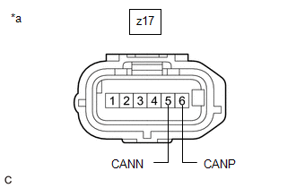
z17-6(CANP) - z17-5(CANN) |
Cable disconnected from negative (-) auxiliary battery terminal |
54 to 69 Ω | |
 |
|
*a | Front view of wire harness connector
(to Swing Grille Actuator Assembly) | | |
| NG |
 | REPAIR OR REPLACE CAN BRANCH LINES OR CONNECTOR (SWING GRILLE ACTUATOR ASSEMBLY) |
|
OK |
 | |
| 2. |
CHECK HARNESS AND CONNECTOR (POWER SOURCE CIRCUIT) |
| (a) Measure the resistance according to the value(s) in the table below.
Standard Resistance: |
Tester Connection | Condition |
Specified Condition | |
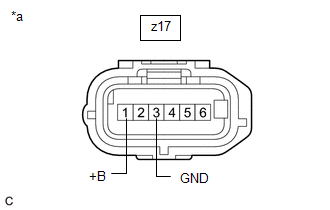
z17-3 (GND) - Body ground |
Cable disconnected from negative (-) auxiliary battery terminal |
Below 1 Ω | |
 |
|
*a | Front view of wire harness connector
(to Swing Grille Actuator Assembly) | | |
(b) Reconnect the cable to the negative (-) auxiliary battery terminal.
(c) Measure the voltage according to the value(s) in the table below.
Standard Voltage:
|
Tester Connection | Condition |
Specified Condition |
|
z17-1 (+B) - Body ground |
Power switch off | 11 to 14 V |
| OK |
| REPLACE SWING GRILLE ACTUATOR ASSEMBLY |
| NG |
| REPAIR OR REPLACE HARNESS OR CONNECTOR (POWER SOURCE CIRCUIT) |
Headlight ECU LH Communication Stop Mode
DESCRIPTION
|
Detection Item | Symptom |
Trouble Area |
| Headlight ECU LH Communication Stop Mode |
Any of the following conditions are met:
- Communication stop for "HL AutoLeveling/AFS/AHS" is indicated on the "Communication Bus Check" screen of the Techstream.
Click here 
- Communication stop history for "HL AutoLeveling/AFS/AHS" is indicated on
the "Communication Bus Check (Detail)" screen of the Techstream. (The
Lost Communication Time value for "HL AutoLeveling/AFS/AHS" is 6 or
more.)
Click here
- Communication system DTCs (DTCs that start with U) that correspond to
"Headlight ECU LH Communication Stop Mode" in "DTC Combination Table"
are output.
Click here
|
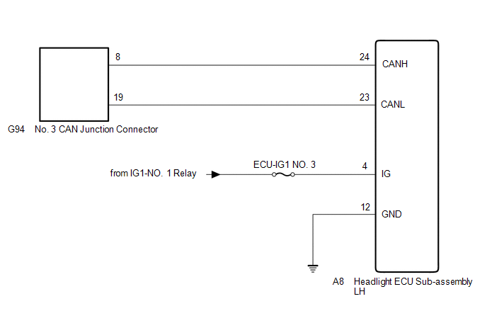
- Headlight ECU sub-assembly LH branch line or connector
- Power source circuit of headlight ECU sub-assembly LH
- Headlight ECU sub-assembly LH ground circuit
- Headlight ECU sub-assembly LH
|
WIRING DIAGRAM
CAUTION / NOTICE / HINT
CAUTION:
When performing the confirmation driving pattern, obey all speed limits and traffic laws.
NOTICE:
HINT:
- Before disconnecting related connectors for inspection, push in on each
connector body to check that the connector is not loose or disconnected.
- When a connector is disconnected, check that the terminals and connector body are not cracked, deformed or corroded.
PROCEDURE
|
1. | CHECK FOR OPEN IN CAN BUS LINES (HEADLIGHT ECU SUB-ASSEMBLY LH BRANCH LINE) |
(a) Disconnect the cable from the negative (-) auxiliary battery terminal.
(b) Disconnect the A8 headlight ECU sub-assembly LH connector.
| (c) Measure the resistance according to the value(s) in the table below.
Standard Resistance: |
Tester Connection | Condition |
Specified Condition | |
A8-24 (CANH) - A8-23 (CANL) |
Cable disconnected from negative (-) auxiliary battery terminal |
54 to 69 Ω | |
 |
|
*a | Front view of wire harness connector
(to Headlight ECU Sub-assembly LH) | | |
| NG |
 | REPAIR OR REPLACE CAN BRANCH LINES OR CONNECTOR (HEADLIGHT ECU SUB-ASSEMBLY LH) |
|
OK |
 | |
| 2. |
CHECK HARNESS AND CONNECTOR (POWER SOURCE CIRCUIT) |
| (a) Measure the resistance according to the value(s) in the table below.
Standard Resistance: |
Tester Connection | Condition |
Specified Condition | |
A8-12 (GND) - Body ground |
Cable disconnected from negative (-) auxiliary battery terminal |
Below 1 Ω | |
 |
|
*a | Front view of wire harness connector
(to Headlight ECU Sub-assembly LH) | | |
(b) Reconnect the cable to the negative (-) auxiliary battery terminal.
(c) Measure the voltage according to the value(s) in the table below.
Standard Voltage:
|
Tester Connection | Condition |
Specified Condition |
|
A8-4 (IG) - Body ground |
Power switch on (IG) |
11 to 14 V |
| OK |
| REPLACE HEADLIGHT ECU SUB-ASSEMBLY LH |
| NG |
| REPAIR OR REPLACE HARNESS OR CONNECTOR (POWER SOURCE CIRCUIT) |
Headlight ECU RH Communication Stop Mode
DESCRIPTION
|
Detection Item | Symptom |
Trouble Area |
| Headlight ECU RH Communication Stop Mode |
Any of the following conditions are met:
- Communication stop for "HL AutoLeveling/AFS/AHS (Sub)" is indicated on the "Communication Bus Check" screen of the Techstream.
Click here 
- Communication stop history for "HL AutoLeveling/AFS/AHS (Sub)" is
indicated on the "Communication Bus Check (Detail)" screen of the
Techstream. (The Lost Communication Time value for "HL
AutoLeveling/AFS/AHS (Sub)" is 6 or more.)
Click here
- Communication system DTCs (DTCs that start with U) that correspond to
"Headlight ECU RH Communication Stop Mode" in "DTC Combination Table"
are output.
Click here
|
- Headlight ECU sub-assembly RH branch line or connector
- Power source circuit of headlight ECU sub-assembly RH
- Headlight ECU sub-assembly RH ground circuit
- Headlight ECU sub-assembly RH
|
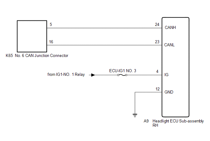
WIRING DIAGRAM
CAUTION / NOTICE / HINT
CAUTION:
When performing the confirmation driving pattern, obey all speed limits and traffic laws.
NOTICE:
HINT:
- Before disconnecting related connectors for inspection, push in on each
connector body to check that the connector is not loose or disconnected.
- When a connector is disconnected, check that the terminals and connector body are not cracked, deformed or corroded.
PROCEDURE
|
1. | CHECK FOR OPEN IN CAN BUS LINES (HEADLIGHT ECU SUB-ASSEMBLY RH BRANCH LINE) |
(a) Disconnect the cable from the negative (-) auxiliary battery terminal.
(b) Disconnect the A9 headlight ECU sub-assembly RH connector.
| (c) Measure the resistance according to the value(s) in the table below.
Standard Resistance: |
Tester Connection | Condition |
Specified Condition | |
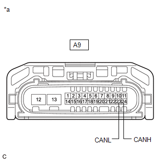
A9-24 (CANH) - A9-23 (CANL) |
Cable disconnected from negative (-) auxiliary battery terminal |
54 to 69 Ω | |
 |
|
*a | Front view of wire harness connector
(to Headlight ECU Sub-assembly RH) | | |
| NG |
 | REPAIR OR REPLACE CAN BRANCH LINES OR CONNECTOR (HEADLIGHT ECU SUB-ASSEMBLY RH) |
|
OK |
 | |
| 2. |
CHECK HARNESS AND CONNECTOR (POWER SOURCE CIRCUIT) |
| (a) Measure the resistance according to the value(s) in the table below.
Standard Resistance: |
Tester Connection | Condition |
Specified Condition | |
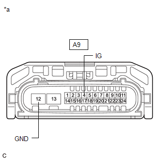
A9-12 (GND) - Body ground |
Cable disconnected from negative (-) auxiliary battery terminal |
Below 1 Ω | |
 |
|
*a | Front view of wire harness connector
(to Headlight ECU Sub-assembly RH) | | |
(b) Reconnect the cable to the negative (-) auxiliary battery terminal.
(c) Measure the voltage according to the value(s) in the table below.
Standard Voltage:
|
Tester Connection | Condition |
Specified Condition |
|
A9-4 (IG) - Body ground |
Power switch on (IG) |
11 to 14 V |
| OK |
| REPLACE HEADLIGHT ECU SUB-ASSEMBLY RH |
| NG |
| REPAIR OR REPLACE HARNESS OR CONNECTOR (POWER SOURCE CIRCUIT) |


