Toyota Avalon (XX50): Clearance Warning ECU Communication Stop Mode. Combination Meter ECU Communication Stop Mode. Data List / Active Test
Clearance Warning ECU Communication Stop Mode
DESCRIPTION
|
Detection Item | Symptom |
Trouble Area |
| Clearance Warning ECU Communication Stop Mode |
Any of the following conditions are met:
- Communication stop for "Clearance Warning (Intuitive Parking Assist)" is
indicated on the "Communication Bus Check" screen of the Techstream.
Click here 
- Communication stop history for "Clearance Warning (Intuitive Parking
Assist)" is indicated on the "Communication Bus Check (Detail)" screen
of the Techstream. (The Lost Communication Time value for "Clearance
Warning (Intuitive Parking Assist)" is 6 or more.)
Click here 
- Communication system DTCs (DTCs that start with U) that correspond to
"Clearance Warning ECU Communication Stop Mode" in "DTC Combination
Table" are output.
Click here 
|
- Clearance warning ECU assembly branch line or connector
- Power source circuit of clearance warning ECU assembly
- Clearance warning ECU assembly ground circuit
- Clearance warning ECU assembly
|
WIRING DIAGRAM
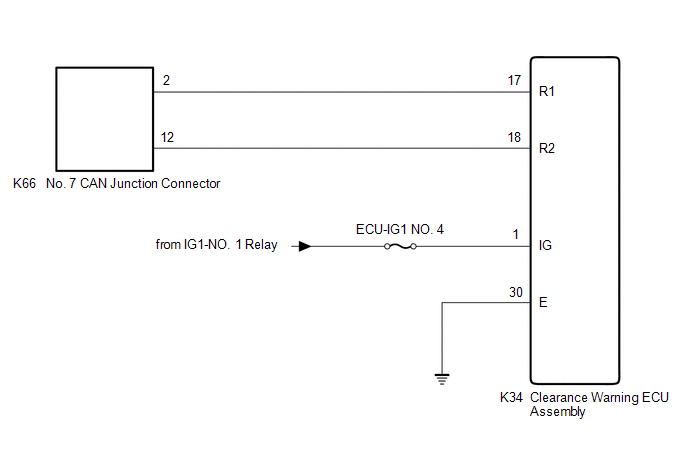
CAUTION / NOTICE / HINT
CAUTION:
When performing the confirmation driving pattern, obey all speed limits and traffic laws.
NOTICE:
HINT:
- Before disconnecting related connectors for inspection, push in on each
connector body to check that the connector is not loose or disconnected.
- When a connector is disconnected, check that the terminals and connector body are not cracked, deformed or corroded.
PROCEDURE
|
1. | CHECK FOR OPEN IN CAN BUS LINES (CLEARANCE WARNING ECU ASSEMBLY BRANCH LINE) |
(a) Disconnect the cable from the negative (-) auxiliary battery terminal.
(b) Disconnect the K34 clearance warning ECU assembly connector.
| (c) Measure the resistance according to the value(s) in the table below.
Standard Resistance: |
Tester Connection | Condition |
Specified Condition | |
K34-17 (R1) - K34-18 (R2) |
Cable disconnected from negative (-) auxiliary battery terminal |
54 to 69 Ω | |
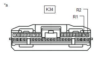 |
|
*a | Front view of wire harness connector
(to Clearance Warning ECU Assembly) | | |
| NG |
 | REPAIR OR REPLACE CAN BRANCH LINES OR CONNECTOR (CLEARANCE WARNING ECU ASSEMBLY) |
|
OK |
 | |
| 2. |
CHECK HARNESS AND CONNECTOR (POWER SOURCE CIRCUIT) |
| (a) Measure the resistance according to the value(s) in the table below.
Standard Resistance: |
Tester Connection | Condition |
Specified Condition | |
K34-30 (E) - Body ground |
Cable disconnected from negative (-) auxiliary battery terminal |
Below 1 Ω | |
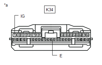 |
|
*a | Front view of wire harness connector
(to Clearance Warning ECU Assembly) | | |
(b) Reconnect the cable to the negative (-) auxiliary battery terminal.
(c) Measure the voltage according to the value(s) in the table below.
Standard Voltage:
|
Tester Connection | Condition |
Specified Condition |
|
K34-1 (IG) - Body ground |
Power switch on (IG) |
11 to 14 V |
| OK |
 | REPLACE CLEARANCE WARNING ECU ASSEMBLY |
| NG |
 | REPAIR OR REPLACE HARNESS OR CONNECTOR (POWER SOURCE CIRCUIT) |
Combination Meter ECU Communication Stop Mode
DESCRIPTION
|
Detection Item | Symptom |
Trouble Area |
| Combination Meter ECU Communication Stop Mode |
Any of the following conditions are met:
- Communication stop for "Combination Meter" is indicated on the "Communication Bus Check" screen of the Techstream.
Click here 
- Communication stop history for "Combination Meter" is indicated on the
"Communication Bus Check (Detail)" screen of the Techstream. (The Lost
Communication Time value for "Combination Meter" is 6 or more.)
Click here 
- Communication system DTCs (DTCs that start with U) that correspond to
"Combination Meter ECU Communication Stop Mode" in "DTC Combination
Table" are output.
Click here 
|
- Combination meter assembly main line or connector
- Power source circuit of combination meter assembly
- Combination meter assembly ground circuit
- Combination meter assembly
|
WIRING DIAGRAM
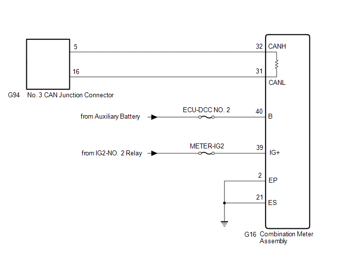
CAUTION / NOTICE / HINT
CAUTION:
When performing the confirmation driving pattern, obey all speed limits and traffic laws.
NOTICE:
HINT:
- Before disconnecting related connectors for inspection, push in on each
connector body to check that the connector is not loose or disconnected.
- When a connector is disconnected, check that the terminals and connector body are not cracked, deformed or corroded.
PROCEDURE
|
1. | CHECK FOR OPEN IN CAN BUS LINES (COMBINATION METER ASSEMBLY MAIN LINE) |
(a) Disconnect the cable from the negative (-) auxiliary battery terminal.
(b) Disconnect the G16 combination meter assembly connector.
| (c) Measure the resistance according to the value(s) in the table below.
Standard Resistance: |
Tester Connection | Condition |
Specified Condition | |
G16-32 (CANH) - G16-31 (CANL) |
Cable disconnected from negative (-) auxiliary battery terminal |
108 to 132 Ω | |
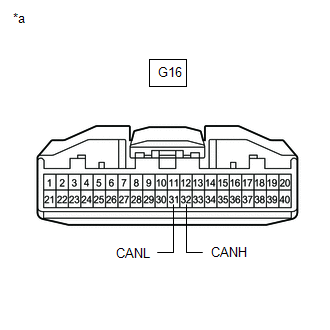 |
|
*a | Front view of wire harness connector
(to Combination Meter Assembly) | | |
| NG |
 | REPAIR OR REPLACE CAN MAIN BUS LINES OR CONNECTOR (COMBINATION METER ASSEMBLY) |
|
OK |
 | |
| 2. |
CHECK HARNESS AND CONNECTOR (POWER SOURCE CIRCUIT) |
| (a) Measure the resistance according to the value(s) in the table below.
Standard Resistance: |
Tester Connection | Condition |
Specified Condition | |
G16-2 (EP) - Body ground |
Cable disconnected from negative (-) auxiliary battery terminal |
Below 1 Ω | |
G16-21 (ES) - Body ground |
Cable disconnected from negative (-) auxiliary battery terminal |
Below 1 Ω | |
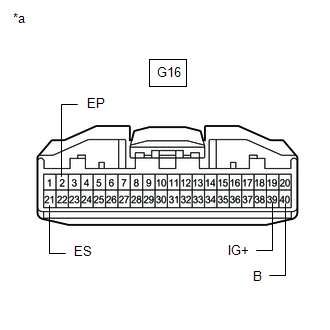 |
|
*a | Front view of wire harness connector
(to Combination Meter Assembly) | | |
(b) Reconnect the cable to the negative (-) auxiliary battery terminal.
(c) Measure the voltage according to the value(s) in the table below.
Standard Voltage:
|
Tester Connection | Condition |
Specified Condition |
|
G16-39 (IG+) - Body ground |
Power switch on (IG) |
11 to 14 V |
|
G16-40 (B) - Body ground |
Power switch off | 11 to 14 V |
| OK |
 | REPLACE COMBINATION METER ASSEMBLY |
| NG |
 | REPAIR OR REPLACE HARNESS OR CONNECTOR (POWER SOURCE CIRCUIT) |
Data List / Active Test
DATA LIST / ACTIVE TEST
NOTICE:
In
the table below, the values listed under "Normal Condition" are
reference values. Do not depend solely on these reference values when
deciding whether a part is faulty or not.
HINT:
Using
the Techstream to read the Data List allows the values or states of
switches, sensors, actuators and other items to be read without removing
any parts. This non-intrusive inspection can be very useful because
intermittent conditions or signals may be discovered before parts or
wiring is disturbed. Reading the Data List information early in
troubleshooting is one way to save diagnostic time.
DATA LIST
(a) Connect the Techstream to the DLC3.
(b) Turn the power switch on (IG).
(c) Turn the Techstream on.
(d) Enter the following menus: Body Electrical / Central Gateway / Data List.
Body Electrical > Central Gateway > Data List
|
Tester Display |
| IG2 SW |
|
IG1 SW |
| ACC SW |
|
+B Voltage |
| Number of DTC |
(e) Read the Data List.
Body Electrical > Central Gateway > Data List
|
Tester Display | Measurement Item |
Range | Normal Condition |
|
IG2 SW | Power switch on (IG) signal (IG2 terminal) |
OFF or ON | OFF: Power switch on (ACC) or off
ON: Power switch on (IG) |
|
IG1 SW | Power switch on (IG) signal (IG1 terminal) |
OFF or ON | OFF: Power switch on (ACC) or off
ON: Power switch on (IG) |
|
ACC SW | Power switch on (ACC) signal (ACC terminal) |
OFF or ON | OFF: Power switch off
ON: Power switch on (ACC) or ON |
|
+B Voltage | Auxiliary battery voltage (BATT terminal) |
Over 8 V or Under 8 V | Over 8 V: Auxiliary battery voltage 8 V or higher
Under 8 V: Auxiliary battery voltage below 8 V |
|
Number of DTC | Number of DTCs |
0 to 255 | 0: Normal |


