DESCRIPTION
There may be a short circuit between one of the CAN bus lines and +B when there is no resistance between terminal 22 (CA2H) of the central gateway ECU (network gateway ECU) and terminal 16 (BAT) of the DLC3, or terminal 7 (CA2L) of the central gateway ECU (network gateway ECU) and terminal 16 (BAT) of the DLC3.
|
Symptom | Trouble Area |
|---|---|
|
There is no resistance between terminal 22 (CA2H) of the central gateway ECU (network gateway ECU) and terminal 16 (BAT) of the DLC3, or terminal 7 (CA2L) of the central gateway ECU (network gateway ECU) and terminal 16 (BAT) of the DLC3. |
|
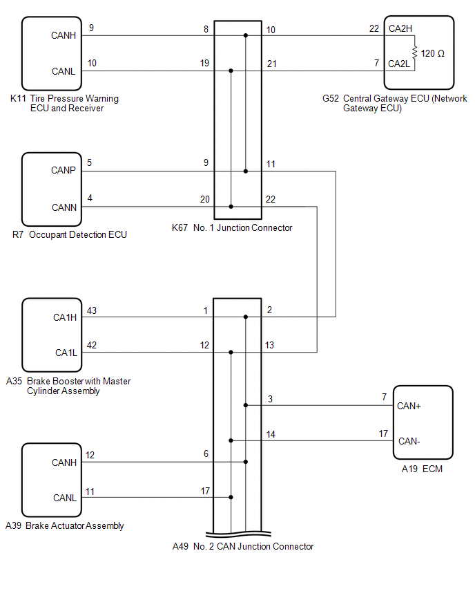
WIRING DIAGRAM
CAUTION / NOTICE / HINT
CAUTION:
When performing the confirmation driving pattern, obey all speed limits and traffic laws.
NOTICE:
Click here 
Click here
DTC check procedure: Turn the power switch on (IG) and wait for 1 minute or more. Then operate the suspected malfunctioning system and drive the vehicle at 60 km/h (37 mph) or more for 5 minutes or more.
Click here
HINT:
PROCEDURE
|
1. | CHECK FOR SHORT TO +B IN CAN BUS LINE (NO. 1 JUNCTION CONNECTOR) |
(a) Disconnect the cable from the negative (-) auxiliary battery terminal.
(b) Disconnect the K67 No. 1 junction connector.
(c) Measure the resistance according to the value(s) in the table below.
|
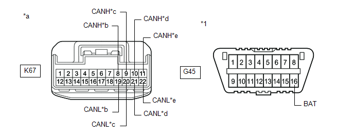
*1 | DLC3 |
- | - |
|
*a | Front view of wire harness connector (to No. 1 Junction Connector) |
*b | to Tire Pressure Warning ECU and Receiver |
|
*c | to Occupant Detection ECU |
*d | to Central Gateway ECU (Network Gateway ECU) |
|
*e | to No. 2 CAN Junction Connector |
- | - |
Standard Resistance:
|
Tester Connection | Condition |
Specified Condition | Connected to |
|---|---|---|---|
|
K67-8 (CANH) - G45-16 (BAT) |
Cable disconnected from negative (-) auxiliary battery terminal |
6 kΩ or higher |
Tire pressure warning ECU and receiver |
|
K67-19 (CANL) - G45-16 (BAT) | |||
|
K67-9 (CANH) - G45-16 (BAT) |
Cable disconnected from negative (-) auxiliary battery terminal |
6 kΩ or higher |
Occupant detection ECU |
|
K67-20 (CANL) - G45-16 (BAT) | |||
|
K67-10 (CANH) - G45-16 (BAT) |
Cable disconnected from negative (-) auxiliary battery terminal |
6 kΩ or higher |
Central gateway ECU (network gateway ECU) |
|
K67-21 (CANL) - G45-16 (BAT) | |||
|
K67-11 (CANH) - G45-16 (BAT) |
Cable disconnected from negative (-) auxiliary battery terminal |
6 kΩ or higher |
No. 2 CAN junction connector |
|
K67-22 (CANL) - G45-16 (BAT) |
|
Result | Proceed to |
|---|---|
|
OK | A |
|
NG (Line to central gateway ECU (network gateway ECU)) |
B |
| NG (Line to No. 2 CAN junction connector) |
C |
| NG (Line to ECU or sensor) |
D |
| A |
 | REPLACE NO. 1 JUNCTION CONNECTOR |
| C |
| GO TO STEP 3 |
| D |
| GO TO STEP 7 |
|
| 2. |
CHECK FOR SHORT TO +B IN CAN BUS LINE (NO. 1 JUNCTION CONNECTOR - CENTRAL GATEWAY ECU (NETWORK GATEWAY ECU)) |
(a) Disconnect the G52 central gateway ECU (network gateway ECU) connector.
(b) Measure the resistance according to the value(s) in the table below.
|
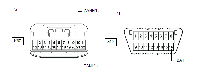
*1 | DLC3 |
- | - |
|
*a | Front view of wire harness connector (to No. 1 Junction Connector) |
*b | to Central Gateway ECU (Network Gateway ECU) |
Standard Resistance:
|
Tester Connection | Condition |
Specified Condition |
|---|---|---|
|
K67-10 (CANH) - G45-16 (BAT) |
Cable disconnected from negative (-) auxiliary battery terminal |
6 kΩ or higher |
|
K67-21 (CANL) - G45-16 (BAT) |
| OK | | REPLACE CENTRAL GATEWAY ECU (NETWORK GATEWAY ECU) |
| NG | | REPAIR OR REPLACE CAN MAIN BUS LINE OR CONNECTOR (NO. 1 JUNCTION CONNECTOR - CENTRAL GATEWAY ECU (NETWORK GATEWAY ECU)) |
| 3. |
CHECK FOR SHORT TO +B IN CAN BUS LINE (NO. 2 CAN JUNCTION CONNECTOR) |
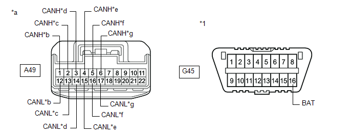
(a) Disconnect the A49 No. 2 CAN junction connector.
(b) Measure the resistance according to the value(s) in the table below.
|
*1 | DLC3 |
- | - |
|
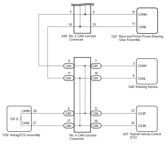
*a | Front view of wire harness connector (to No. 2 CAN Junction Connector) |
*b | to Brake Booster with Master Cylinder Assembly |
|
*c | to No. 1 Junction Connector |
*d | to ECM |
|
*e | to Rack and Pinion Power Steering Gear Assembly |
*f | to No. 4 CAN Junction Connector |
|
*g | to Brake Actuator Assembly |
- | - |
Standard Resistance:
|
Tester Connection | Condition |
Specified Condition | Connected to |
|---|---|---|---|
|
A49-1 (CANH) - G45-16 (BAT) |
Cable disconnected from negative (-) auxiliary battery terminal |
6 kΩ or higher |
Brake booster with master cylinder assembly |
|
A49-12 (CANL) - G45-16 (BAT) | |||
|
A49-2 (CANH) - G45-16 (BAT) |
Cable disconnected from negative (-) auxiliary battery terminal |
6 kΩ or higher |
No. 1 junction connector |
|
A49-13 (CANL) - G45-16 (BAT) | |||
|
A49-3 (CANH) - G45-16 (BAT) |
Cable disconnected from negative (-) auxiliary battery terminal |
6 kΩ or higher |
ECM |
| A49-14 (CANL) - G45-16 (BAT) | |||
|
A49-4 (CANH) - G45-16 (BAT) |
Cable disconnected from negative (-) auxiliary battery terminal |
6 kΩ or higher |
Rack and pinion power steering gear assembly |
|
A49-15 (CANL) - G45-16 (BAT) | |||
|
A49-5 (CANH) - G45-16 (BAT) |
Cable disconnected from negative (-) auxiliary battery terminal |
6 kΩ or higher |
No. 4 CAN junction connector |
|
A49-16 (CANL) - G45-16 (BAT) | |||
|
A49-6 (CANH) - G45-16 (BAT) |
Cable disconnected from negative (-) auxiliary battery terminal |
6 kΩ or higher |
Brake actuator assembly |
|
A49-17 (CANL) - G45-16 (BAT) |
|
Result | Proceed to |
|---|---|
|
OK | A |
|
NG (Line to No. 1 junction connector) |
B |
| NG (Line to No. 4 CAN junction connector) |
C |
| NG (Line to ECU or sensor) |
D |
| A |
| REPLACE NO. 2 CAN JUNCTION CONNECTOR |
| B |
| REPAIR OR REPLACE CAN MAIN BUS LINE OR CONNECTOR (NO. 2 CAN JUNCTION CONNECTOR - NO. 1 JUNCTION CONNECTOR) |
| D |
| GO TO STEP 7 |
|
| 4. |
CHECK FOR SHORT TO +B IN CAN BUS LINE (NO. 4 CAN JUNCTION CONNECTOR) |
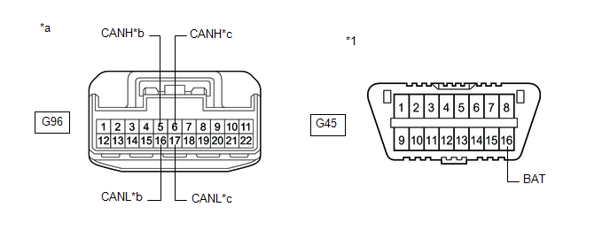
(a) Disconnect the G96 No. 4 CAN junction connector.
(b) Measure the resistance according to the value(s) in the table below.
|
*1 | DLC3 |
- | - |
|
*a | Front view of wire harness connector (to No. 4 CAN Junction Connector) |
*b | to Hybrid Vehicle Control ECU |
|
*c | to Airbag ECU Assembly |
- | - |
Standard Resistance:
|
Tester Connection | Condition |
Specified Condition | Connected to |
|---|---|---|---|
|
G96-5 (CANH) - G45-16 (BAT) |
Cable disconnected from negative (-) auxiliary battery terminal |
6 kΩ or higher |
Hybrid vehicle control ECU |
|
G96-16 (CANL) - G45-16 (BAT) | |||
|
G96-6 (CANH) - G45-16 (BAT) |
Cable disconnected from negative (-) auxiliary battery terminal |
6 kΩ or higher |
Airbag ECU assembly |
|
G96-17 (CANL) - G45-16 (BAT) |
|
Result | Proceed to |
|---|---|
|
OK | A |
|
NG (Line to airbag ECU assembly) |
B |
| NG (Line to ECU or sensor) |
C |
| B |
| GO TO STEP 6 |
| C |
| GO TO STEP 7 |
|
| 5. |
CHECK FOR SHORT TO +B IN CAN BUS LINE (NO. 4 CAN JUNCTION CONNECTOR) |
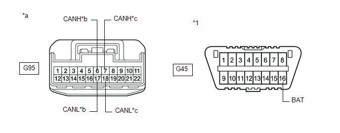
(a) Disconnect the G95 No. 4 CAN junction connector.
(b) Measure the resistance according to the value(s) in the table below.
|
*1 | DLC3 |
- | - |
|
*a | Front view of wire harness connector (to No. 4 CAN Junction Connector) |
*b | to No. 2 CAN Junction Connector |
|
*c | to Steering Sensor |
- | - |
Standard Resistance:
|
Tester Connection | Condition |
Specified Condition | Connected to |
|---|---|---|---|
|
G95-6 (CANH) - G45-16 (BAT) |
Cable disconnected from negative (-) auxiliary battery terminal |
6 kΩ or higher |
No. 2 CAN junction connector |
|
G95-17 (CANL) - G45-16 (BAT) | |||
|
G95-7 (CANH) - G45-16 (BAT) |
Cable disconnected from negative (-) auxiliary battery terminal |
6 kΩ or higher |
Steering sensor |
|
G95-18 (CANL) - G45-16 (BAT) |
|
Result | Proceed to |
|---|---|
|
OK | A |
|
NG (Line to No. 2 CAN junction connector) |
B |
| NG (Line to ECU or sensor) |
C |
| A |
| REPLACE NO. 4 CAN JUNCTION CONNECTOR |
| B |
| REPAIR OR REPLACE CAN MAIN BUS LINE OR CONNECTOR (NO. 4 CAN JUNCTION CONNECTOR - NO. 2 CAN JUNCTION CONNECTOR) |
| C |
| GO TO STEP 7 |
| 6. |
CHECK FOR SHORT TO +B IN CAN BUS LINE (NO. 4 CAN JUNCTION CONNECTOR - AIRBAG ECU ASSEMBLY) |
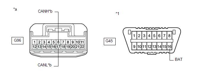
(a) Disconnect the G50 airbag ECU assembly connector.
(b) Measure the resistance according to the value(s) in the table below.
|
*1 | DLC3 |
- | - |
|
*a | Front view of wire harness connector (to No. 4 CAN Junction Connector) |
*b | to Airbag ECU Assembly |
Standard Resistance:
|
Tester Connection | Condition |
Specified Condition |
|---|---|---|
|
G96-6 (CANH) - G45-16 (BAT) |
Cable disconnected from negative (-) auxiliary battery terminal |
6 kΩ or higher |
|
G96-17 (CANL) - G45-16 (BAT) |
| OK | | REPLACE AIRBAG ECU ASSEMBLY |
| NG | | REPAIR OR REPLACE CAN MAIN BUS LINE OR CONNECTOR (NO. 4 CAN JUNCTION CONNECTOR - AIRBAG ECU ASSEMBLY) |
| 7. |
CHECK FOR SHORT TO +B IN CAN BUS LINE (ECU OR SENSOR) |
(a) Reconnect all wire harness connectors.
(b) Disconnect the connector that includes terminals CANH and CANL from the ECU or sensor to which the bus line shorted to +B is connected.
Click here
(c) Measure the resistance according to the value(s) in the table below.
|
*1 | DLC3 |
- | - |
|
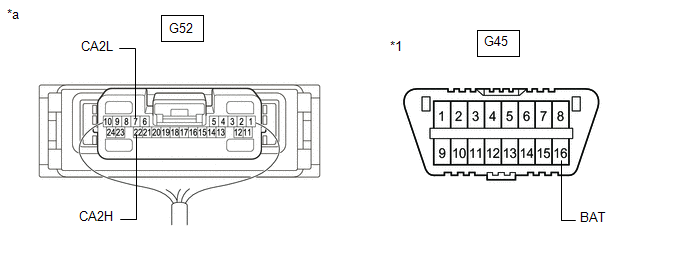
*a | Component with harness connected (Central Gateway ECU (Network Gateway ECU)) |
- | - |
Standard Resistance:
|
Tester Connection | Condition |
Specified Condition |
|---|---|---|
|
G52-22 (CA2H) - G45-16 (BAT) |
Cable disconnected from negative (-) auxiliary battery terminal |
6 kΩ or higher |
|
G52-7 (CA2L) - G45-16 (BAT) |
HINT:
| OK | | REPLACE ECU OR SENSOR |
| NG | | REPAIR OR REPLACE HARNESS OR CONNECTOR |
Toyota Avalon (XX50) 2019-2022 Service & Repair Manual > Steering Column: Steering Column Assembly(for Manual Tilt And Manual Telescopic Steering Column)
Components COMPONENTS ILLUSTRATION *1 STEERING WHEEL ASSEMBLY - - Tightening torque for "Major areas involving basic vehicle performance such as moving/turning/stopping": N*m (kgf*cm, ft.*lbf) - - ILLUSTRATION *1 LOWER STEERING COLUMN COVER *2 TURN SIGNAL SWITCH ASSEMBLY WITH SPIRAL CABLE SUB-ASSEMB ...


