DESCRIPTION
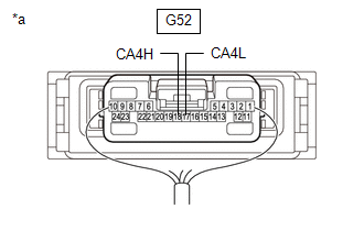
There may be a short circuit between the CAN main bus lines and/or CAN branch lines when the resistance between terminals 18 (CA4H) and 17 (CA4L) of the central gateway ECU (network gateway ECU) is below 54 Ω.
|
Symptom | Trouble Area |
|---|---|
|
Resistance between terminals 18 (CA4H) and 17 (CA4L) of the central gateway ECU (network gateway ECU) is below 54 Ω. |
|
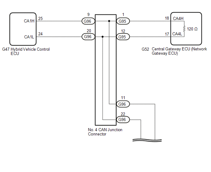
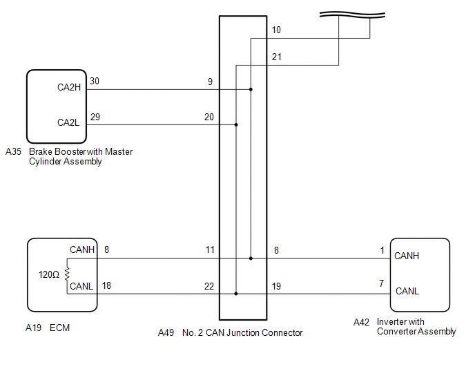
WIRING DIAGRAM
CAUTION / NOTICE / HINT
CAUTION:
When performing the confirmation driving pattern, obey all speed limits and traffic laws.
NOTICE:
Click here 
Click here
DTC check procedure: Turn the power switch on (IG) and wait for 1 minute or more. Then operate the suspected malfunctioning system and drive the vehicle at 60 km/h (37 mph) or more for 5 minutes or more.
Click here
HINT:
PROCEDURE
|
1. | CHECK FOR SHORT IN CAN BUS LINES (NO. 2 CAN JUNCTION CONNECTOR) |
(a) Disconnect the cable from the negative (-) auxiliary battery terminal.
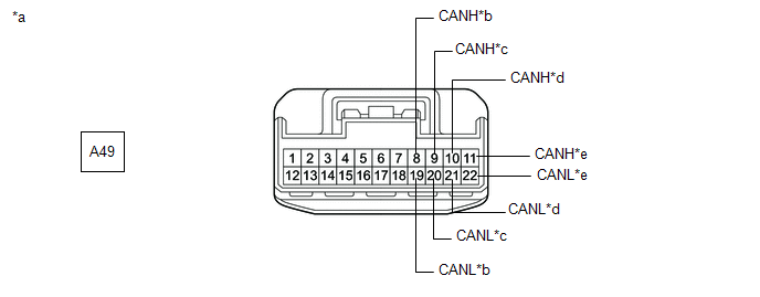
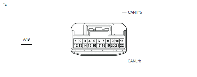
(b) Disconnect the A49 No. 2 CAN junction connector.
(c) Measure the resistance according to the value(s) in the table below.
|
*a | Front view of wire harness connector (to No. 2 CAN Junction Connector) |
*b | to Inverter with Converter Assembly |
|
*c | to Brake Booster with Master Cylinder Assembly |
*d | to No. 4 CAN Junction Connector |
|
*e | to ECM |
- | - |
Standard Resistance:
|
Tester Connection | Condition |
Specified Condition | Connected to |
|---|---|---|---|
|
A49-8 (CANH) - A49-19 (CANL) |
Cable disconnected from negative (-) auxiliary battery terminal |
200 Ω or higher | Inverter with converter assembly |
|
A49-9 (CANH) - A49-20 (CANL) |
Cable disconnected from negative (-) auxiliary battery terminal |
200 Ω or higher | Brake booster with master cylinder assembly |
|
A49-10 (CANH) - A49-21 (CANL) |
Cable disconnected from negative (-) auxiliary battery terminal |
108 to 132 Ω | No. 4 CAN junction connector |
|
A49-11 (CANH) - A49-22 (CANL) |
Cable disconnected from negative (-) auxiliary battery terminal |
108 to 132 Ω | ECM |
|
Result | Proceed to |
|---|---|
|
OK | A |
|
NG (Line to ECM) | B |
|
NG (Line to No. 4 CAN junction connector) |
C |
| NG (Line to ECU or sensor) |
D |
| A |
 | REPLACE NO. 2 CAN JUNCTION CONNECTOR |
| C |
| GO TO STEP 3 |
| D |
| GO TO STEP 6 |
|
| 2. |
CHECK FOR SHORT IN CAN BUS LINES (NO. 2 CAN JUNCTION CONNECTOR - ECM) |
(a) Disconnect the A19 ECM connector.
(b) Measure the resistance according to the value(s) in the table below.
|
*a | Front view of wire harness connector (to No. 2 CAN Junction Connector) |
*b | to ECM |
Standard Resistance:
|
Tester Connection | Condition |
Specified Condition |
|---|---|---|
|
A49-11 (CANH) - A49-22 (CANL) |
Cable disconnected from negative (-) auxiliary battery terminal |
1 MΩ or higher |
| OK | | REPLACE ECM |
| NG | | REPAIR OR REPLACE CAN MAIN BUS LINES OR CONNECTOR (NO. 2 CAN JUNCTION CONNECTOR - ECM) |
| 3. |
CHECK FOR SHORT IN CAN BUS LINES (NO. 4 CAN JUNCTION CONNECTOR - NO. 2 CAN JUNCTION CONNECTOR) |
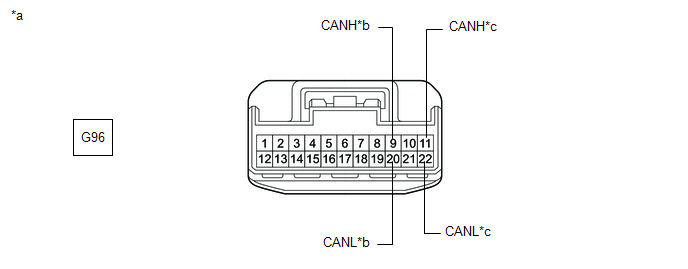
(a) Disconnect the G96 No. 4 CAN junction connector.
(b) Measure the resistance according to the value(s) in the table below.
|
*a | Front view of wire harness connector (to No. 4 CAN Junction Connector) |
*b | to Hybrid Vehicle Control ECU |
|
*c | to No. 2 CAN Junction Connector |
- | - |
Standard Resistance:
|
Tester Connection | Condition |
Specified Condition | Connected to |
|---|---|---|---|
|
G96-9 (CANH) - G96-20 (CANL) |
Cable disconnected from negative (-) auxiliary battery terminal |
200 Ω or higher | Hybrid vehicle control ECU |
|
G96-11 (CANH) - G96-22 (CANL) |
Cable disconnected from negative (-) auxiliary battery terminal |
1 MΩ or higher | No. 2 CAN junction connector |
|
Result | Proceed to |
|---|---|
|
OK | A |
|
NG (Line to No. 2 CAN junction connector) |
B |
| NG (Line to ECU or sensor) |
C |
| B |
| REPAIR OR REPLACE CAN MAIN BUS LINES OR CONNECTOR (NO. 4 CAN JUNCTION CONNECTOR - NO. 2 CAN JUNCTION CONNECTOR) |
| C |
| GO TO STEP 6 |
|
| 4. |
CHECK FOR SHORT IN CAN BUS LINES (NO. 4 CAN JUNCTION CONNECTOR) |
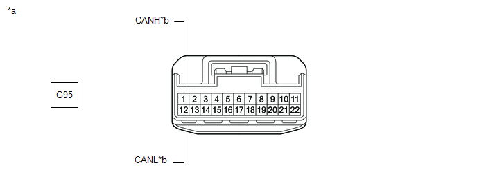
(a) Disconnect the G95 No. 4 CAN junction connector.
(b) Measure the resistance according to the value(s) in the table below.
|
*a | Front view of wire harness connector (to No. 4 CAN Junction Connector) |
*b | to Central Gateway ECU (Network Gateway ECU) |
Standard Resistance:
|
Tester Connection | Condition |
Specified Condition |
|---|---|---|
|
G95-1 (CANH) - G95-12 (CANL) |
Cable disconnected from negative (-) auxiliary battery terminal |
108 to 132 Ω |
| OK | | REPLACE NO. 4 CAN JUNCTION CONNECTOR |
|
| 5. |
CHECK FOR SHORT IN CAN BUS LINES (NO. 4 CAN JUNCTION CONNECTOR - CENTRAL GATEWAY ECU (NETWORK GATEWAY ECU)) |
(a) Disconnect the G52 central gateway ECU (network gateway ECU) connector.
(b) Measure the resistance according to the value(s) in the table below.
|
*a | Front view of wire harness connector (to No. 4 CAN Junction Connector) |
*b | to Central Gateway ECU (Network Gateway ECU) |
Standard Resistance:
|
Tester Connection | Condition |
Specified Condition |
|---|---|---|
|
G95-1 (CANH) - G95-12 (CANL) |
Cable disconnected from negative (-) auxiliary battery terminal |
1 MΩ or higher |
| OK | | REPLACE CENTRAL GATEWAY ECU (NETWORK GATEWAY ECU) |
| NG | | REPAIR OR REPLACE CAN MAIN BUS LINES OR CONNECTOR (NO. 4 CAN JUNCTION CONNECTOR - CENTRAL GATEWAY ECU (NETWORK GATEWAY ECU)) |
| 6. |
CHECK FOR SHORT IN CAN BUS LINES (ECU OR SENSOR) |
(a) Reconnect all wire harness connectors.
(b) Disconnect the connector that includes terminals CANH and CANL from the ECU or sensor to which the short circuited branch line is connected.
Click here
| (c) Measure the resistance according to the value(s) in the table below. Standard Resistance:
HINT:
|
|
| OK | | REPLACE ECU OR SENSOR |
| NG | | REPAIR OR REPLACE HARNESS OR CONNECTOR |
Toyota Avalon (XX50) 2019-2022 Service & Repair Manual > Parking Brake: Parking Brake System
PrecautionPRECAUTION NOTICE: If the battery is connected, the parking brake will operate when the electric parking brake switch assembly is pulled to the lock side even if the engine switch (for Gasoline Model) or power switch (for HV Model) is off. Do not operate the electric parking brake switch ...