Open in Bus 1 Main Bus Line
DESCRIPTION
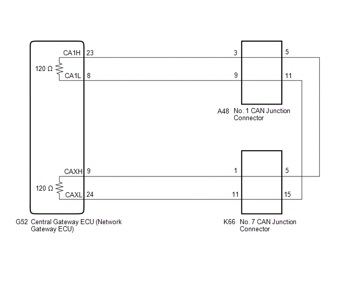
There may be an
open circuit in one of the CAN main bus lines when the resistance
between terminals 23 (CA1H) and 8 (CA1L) of the central gateway ECU
(network gateway ECU) is 70 Ω or higher.
|
Symptom | Trouble Area |
|
Resistance between terminals 23 (CA1H) and 8 (CA1L) of the central gateway ECU (network gateway ECU) is 70 Ω or higher. |
- CAN main bus lines or connector
- Central gateway ECU (network gateway ECU)
- No. 1 CAN junction connector
- No. 7 CAN junction connector
|
This malfunction is not related to the lines of a CAN branch or to ECUs or sensors connected to a CAN branch.
WIRING DIAGRAM
CAUTION / NOTICE / HINT
CAUTION:
When performing the confirmation driving pattern, obey all speed limits and traffic laws.
NOTICE:
HINT:
- Before disconnecting related connectors for inspection, push in on each
connector body to check that the connector is not loose or disconnected.
- When a connector is disconnected, check that the terminals and connector body are not cracked, deformed or corroded.
PROCEDURE
|
1. | CHECK FOR OPEN IN CAN MAIN BUS LINES (NO. 1 CAN JUNCTION CONNECTOR) |
(a) Disconnect the cable from the negative (-) battery terminal.
(b) Disconnect the A48 No. 1 CAN junction connector.
(c) Measure the resistance according to the value(s) in the table below.
|
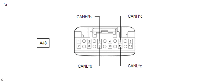
*a | Front view of wire harness connector
(to No. 1 CAN Junction Connector) |
*b | to Central Gateway ECU (Network Gateway ECU) |
|
*c | to No. 7 CAN Junction Connector |
- | - |
Standard Resistance:
|
Tester Connection | Condition |
Specified Condition | Connected to |
|
A48-3 (CANH) - A48-9 (CANL) |
Cable disconnected from negative (-) battery terminal |
108 to 132 Ω | Central gateway ECU (network gateway ECU) |
|
A48-5 (CANH) - A48-11 (CANL) |
Cable disconnected from negative (-) battery terminal |
108 to 132 Ω | No. 7 CAN junction connector |
|
Result | Proceed to |
|
OK | A |
|
NG (Line to central gateway ECU (network gateway ECU)) |
B |
| NG (Line to No. 7 CAN junction connector) |
C |
| A |
 | REPLACE NO. 1 CAN JUNCTION CONNECTOR |
| C |
| GO TO STEP 3 |
|
B |
 | |
| 2. |
CHECK FOR OPEN IN CAN MAIN BUS LINES (CENTRAL GATEWAY ECU (NETWORK GATEWAY ECU) - NO. 1 CAN JUNCTION CONNECTOR) |
(a) Reconnect the A48 No. 1 CAN junction connector.
(b) Disconnect the G52 central gateway ECU (network gateway ECU) connector.
| (c) Measure the resistance according to the value(s) in the table below.
Standard Resistance: |
Tester Connection | Condition |
Specified Condition | |
G52-23 (CA1H) - G52-9 (CAXH) |
Cable disconnected from negative (-) battery terminal |
Below 1 Ω | |
G52-8 (CA1L) - G52-24 (CAXL) |
Cable disconnected from negative (-) battery terminal |
Below 1 Ω | |
 |
|
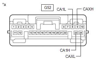
*a | Front view of wire harness connector
(to Central Gateway ECU (Network Gateway ECU)) | | |
| OK |
| REPLACE CENTRAL GATEWAY ECU (NETWORK GATEWAY ECU) |
| NG |
| REPAIR OR REPLACE CAN MAIN BUS LINES OR CONNECTOR (CENTRAL GATEWAY ECU (NETWORK GATEWAY ECU) - NO. 1 CAN JUNCTION CONNECTOR) |
| 3. |
CHECK FOR OPEN IN CAN MAIN BUS LINES (NO. 7 CAN JUNCTION CONNECTOR) |
(a) Reconnect the A48 No. 1 CAN junction connector.
(b) Disconnect the K66 No. 7 CAN junction connector.
(c) Measure the resistance according to the value(s) in the table below.
|
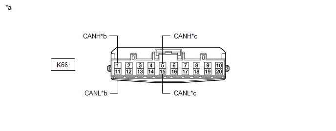
*a | Front view of wire harness connector
(to No. 7 CAN Junction Connector) |
*b | to Central Gateway ECU (Network Gateway ECU) |
|
*c | to No. 1 CAN Junction Connector |
- | - |
Standard Resistance:
|
Tester Connection | Condition |
Specified Condition | Connected to |
|
K66-1 (CANH) - K66-11 (CANL) |
Cable disconnected from negative (-) battery terminal |
108 to 132 Ω | Central gateway ECU (network gateway ECU) |
|
K66-5 (CANH) - K66-15 (CANL) |
Cable disconnected from negative (-) battery terminal |
108 to 132 Ω | No. 1 CAN junction connector |
|
Result | Proceed to |
|
OK | A |
|
NG (Line to No. 1 CAN junction connector) |
B |
| NG (Line to central gateway ECU (network gateway ECU)) |
C |
| A |
| REPLACE NO. 7 CAN JUNCTION CONNECTOR |
| B |
| REPAIR OR REPLACE CAN MAIN BUS LINES OR CONNECTOR (NO. 7 CAN JUNCTION CONNECTOR - NO. 1 CAN JUNCTION CONNECTOR) |
|
C | |
| |
| 4. |
CHECK FOR OPEN IN CAN MAIN BUS LINES (CENTRAL GATEWAY ECU (NETWORK GATEWAY ECU) - NO. 7 CAN JUNCTION CONNECTOR) |
(a) Reconnect the K66 No. 7 CAN junction connector.
(b) Disconnect the G52 central gateway ECU (network gateway ECU) connector.
| (c) Measure the resistance according to the value(s) in the table below.
Standard Resistance: |
Tester Connection | Condition |
Specified Condition | |
G52-23 (CA1H) - G52-9 (CAXH) |
Cable disconnected from negative (-) battery terminal |
Below 1 Ω | |
G52-8 (CA1L) - G52-24 (CAXL) |
Cable disconnected from negative (-) battery terminal |
Below 1 Ω | | |
|
|
*a | Front view of wire harness connector
(to Central Gateway ECU (Network Gateway ECU)) | | |
| OK |
| REPLACE CENTRAL GATEWAY ECU (NETWORK GATEWAY ECU) |
| NG |
| REPAIR OR REPLACE CAN MAIN BUS LINES OR CONNECTOR (CENTRAL GATEWAY ECU (NETWORK GATEWAY ECU) - NO. 7 CAN JUNCTION CONNECTOR) |
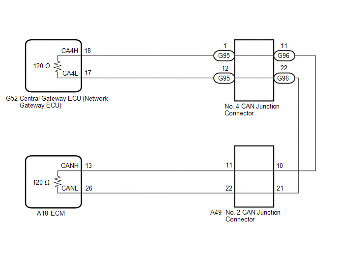
Open in Bus 2 Main Bus Line
DESCRIPTION
There may be an
open circuit in one of the CAN main bus lines when the resistance
between terminals 18 (CA4H) and 17 (CA4L) of the central gateway ECU
(network gateway ECU) is 70 Ω or higher.
|
Symptom | Trouble Area |
|
Resistance between terminals 18 (CA4H) and 17 (CA4L) of the central gateway ECU (network gateway ECU) is 70 Ω or higher. |
- CAN main bus lines or connector
- Central gateway ECU (network gateway ECU)
- ECM
- No. 2 CAN junction connector
- No. 4 CAN junction connector
|
This malfunction is not related to the lines of a CAN branch or to ECUs or sensors connected to a CAN branch.
WIRING DIAGRAM
CAUTION / NOTICE / HINT
CAUTION:
When performing the confirmation driving pattern, obey all speed limits and traffic laws.
NOTICE:
HINT:
- Before disconnecting related connectors for inspection, push in on each
connector body to check that the connector is not loose or disconnected.
- When a connector is disconnected, check that the terminals and connector body are not cracked, deformed or corroded.
PROCEDURE
|
1. | CHECK FOR OPEN IN CAN MAIN BUS LINES (NO. 2 CAN JUNCTION CONNECTOR) |
(a) Disconnect the cable from the negative (-) battery terminal.
(b) Disconnect the A49 No. 2 CAN junction connector.
(c) Measure the resistance according to the value(s) in the table below.
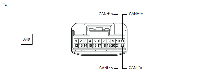
|
*a | Front view of wire harness connector
(to No. 2 CAN Junction Connector) |
*b | to No. 4 CAN Junction Connector |
|
*c | to ECM |
- | - |
Standard Resistance:
|
Tester Connection | Condition |
Specified Condition | Connected to |
|
A49-10 (CANH) - A49-21 (CANL) |
Cable disconnected from negative (-) battery terminal |
108 to 132 Ω | No. 4 CAN junction connector |
|
A49-11 (CANH) - A49-22 (CANL) |
Cable disconnected from negative (-) battery terminal |
108 to 132 Ω | ECM |
|
Result | Proceed to |
|
OK | A |
|
NG (Line to ECM) | B |
|
NG (Line to No. 4 CAN junction connector) |
C |
| A |
 | REPLACE NO. 2 CAN JUNCTION CONNECTOR |
| C |
| GO TO STEP 3 |
|
B |
 | |
| 2. |
CHECK FOR OPEN IN CAN MAIN BUS LINES (ECM - NO. 2 CAN JUNCTION CONNECTOR) |
(a) Reconnect the A49 No. 2 CAN junction connector.
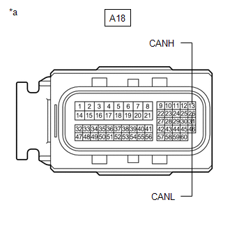
(b) Disconnect the A18 ECM connector.
| (c) Measure the resistance according to the value(s) in the table below.
Standard Resistance: |
Tester Connection | Condition |
Specified Condition | |
A18-13 (CANH) - A18-26 (CANL) |
Cable disconnected from negative (-) battery terminal |
108 to 132 Ω | |
 |
|
*a | Front view of wire harness connector
(to ECM) | | |
| OK |
| REPLACE ECM |
| NG |
| REPAIR OR REPLACE CAN MAIN BUS LINES OR CONNECTOR (ECM - NO. 2 CAN JUNCTION CONNECTOR) |
| 3. |
CHECK FOR OPEN IN CAN MAIN BUS LINES (NO. 4 CAN JUNCTION CONNECTOR - NO. 2 CAN JUNCTION CONNECTOR) |
(a) Reconnect the A49 No. 2 CAN junction connector.
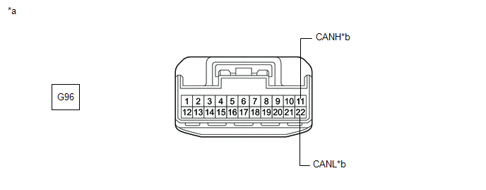
(b) Disconnect the G96 No. 4 CAN junction connector.
(c) Measure the resistance according to the value(s) in the table below.
|
*a | Front view of wire harness connector
(to No. 4 CAN Junction Connector) |
*b | to No. 2 CAN Junction Connector |
Standard Resistance:
|
Tester Connection | Condition |
Specified Condition |
|
G96-11 (CANH) - G96-22 (CANL) |
Cable disconnected from negative (-) battery terminal |
108 to 132 Ω |
| NG |
| REPAIR OR REPLACE CAN MAIN BUS LINES OR CONNECTOR (NO. 4 CAN JUNCTION CONNECTOR - NO. 2 CAN JUNCTION CONNECTOR) |
|
OK | |
| |
| 4. |
CHECK FOR OPEN IN CAN MAIN BUS LINES (NO. 4 CAN JUNCTION CONNECTOR) |
(a) Reconnect the G96 No. 4 CAN junction connector.
(b) Disconnect the G95 No. 4 CAN junction connector.
(c) Measure the resistance according to the value(s) in the table below.
|
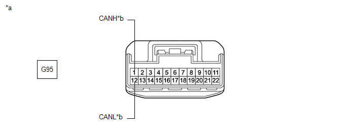
*a | Front view of wire harness connector
(to No. 4 CAN Junction Connector) |
*b | to Central Gateway ECU (Network Gateway ECU) |
Standard Resistance:
|
Tester Connection | Condition |
Specified Condition |
|
G95-1 (CANH) - G95-12 (CANL) |
Cable disconnected from negative (-) battery terminal |
108 to 132 Ω |
| OK |
| REPLACE NO. 4 CAN JUNCTION CONNECTOR |
|
NG | |
| |
| 5. |
CHECK FOR OPEN IN CAN MAIN BUS LINES (CENTRAL GATEWAY ECU (NETWORK GATEWAY ECU) - NO. 4 CAN JUNCTION CONNECTOR) |
(a) Reconnect the G95 No. 4 CAN junction connector.
(b) Disconnect the G52 central gateway ECU (network gateway ECU) connector.
| (c) Measure the resistance according to the value(s) in the table below.
Standard Resistance: |
Tester Connection | Condition |
Specified Condition | |
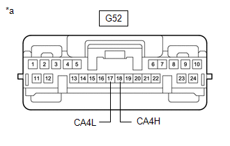
G52-18 (CA4H) - G52-17 (CA4L) |
Cable disconnected from negative (-) battery terminal |
108 to 132 Ω | |
 |
|
*a | Front view of wire harness connector
(to Central Gateway ECU (Network Gateway ECU)) | | |
| OK |
| REPLACE CENTRAL GATEWAY ECU (NETWORK GATEWAY ECU) |
| NG |
| REPAIR OR REPLACE CAN MAIN BUS LINES OR CONNECTOR (CENTRAL GATEWAY ECU (NETWORK GATEWAY ECU) - NO. 4 CAN JUNCTION CONNECTOR) |
Open in Bus 3 Main Bus Line
DESCRIPTION
There may be an
open circuit in one of the CAN main bus lines when the resistance
between terminals 6 (CA3H) and 21 (CA3L) of the central gateway ECU
(network gateway ECU) is 70 Ω or higher.
|
Symptom | Trouble Area |
|
Resistance between terminals 6 (CA3H) and 21 (CA3L) of the central gateway ECU (network gateway ECU) is 70 Ω or higher. |
- CAN main bus lines or connector
- Central gateway ECU (network gateway ECU)
- No. 4 CAN junction connector
|
This malfunction is not related to the lines of a CAN branch or to ECUs or sensors connected to a CAN branch.
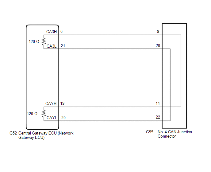
WIRING DIAGRAM
CAUTION / NOTICE / HINT
CAUTION:
When performing the confirmation driving pattern, obey all speed limits and traffic laws.
NOTICE:
HINT:
- Before disconnecting related connectors for inspection, push in on each
connector body to check that the connector is not loose or disconnected.
- When a connector is disconnected, check that the terminals and connector body are not cracked, deformed or corroded.
PROCEDURE
|
1. | CHECK FOR OPEN IN CAN MAIN BUS LINES (NO. 4 CAN JUNCTION CONNECTOR) |
(a) Disconnect the cable from the negative (-) battery terminal.
(b) Disconnect the G95 No. 4 CAN junction connector.
(c) Measure the resistance according to the value(s) in the table below.
|
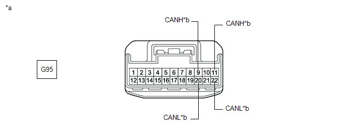
*a | Front view of wire harness connector
(to No. 4 CAN Junction Connector) |
*b | to Central Gateway ECU (Network Gateway ECU) |
Standard Resistance:
|
Tester Connection | Condition |
Specified Condition | Connected to |
|
G95-9 (CANH) - G95-20 (CANL) |
Cable disconnected from negative (-) battery terminal |
108 to 132 Ω | Central gateway ECU (network gateway ECU) |
|
G95-11 (CANH) - G95-22 (CANL) |
Cable disconnected from negative (-) battery terminal |
108 to 132 Ω | Central gateway ECU (network gateway ECU) |
| OK |
 | REPLACE NO. 4 CAN JUNCTION CONNECTOR |
|
NG |
 | |
| 2. |
CHECK FOR OPEN IN CAN MAIN BUS LINES (CENTRAL GATEWAY ECU (NETWORK GATEWAY ECU) - NO. 4 CAN JUNCTION CONNECTOR) |
(a) Reconnect the G95 No. 4 CAN junction connector.
(b) Disconnect the G52 central gateway ECU (network gateway ECU) connector.
| (c) Measure the resistance according to the value(s) in the table below.
Standard Resistance: |
Tester Connection | Condition |
Specified Condition | |
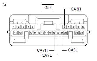
G52-6 (CA3H) - G52-19 (CAYH) |
Cable disconnected from negative (-) battery terminal |
Below 1 Ω | |
G52-21 (CA3L) - G52-20 (CAYL) |
Cable disconnected from negative (-) battery terminal |
Below 1 Ω | |
 |
|
*a | Front view of wire harness connector
(to Central gateway ECU (network gateway ECU)) | | |
| OK |
| REPLACE CENTRAL GATEWAY ECU (NETWORK GATEWAY ECU) |
| NG |
| REPAIR OR REPLACE CAN MAIN BUS LINES OR CONNECTOR (CENTRAL GATEWAY ECU (NETWORK GATEWAY ECU) - NO. 4 CAN JUNCTION CONNECTOR) |


