DESCRIPTION
There may be a short circuit between one of the CAN bus lines and +B when there is no resistance between terminal 23 (CA1H) of the central gateway ECU (network gateway ECU) and terminal 16 (BAT) of the DLC3, or terminal 8 (CA1L) of the central gateway ECU (network gateway ECU) and terminal 16 (BAT) of the DLC3.
|
Symptom | Trouble Area |
|---|---|
|
There is no resistance between terminal 23 (CA1H) of the central gateway ECU (network gateway ECU) and terminal 16 (BAT) of the DLC3, or terminal 8 (CA1L) of the central gateway ECU (network gateway ECU) and terminal 16 (BAT) of the DLC3. |
|
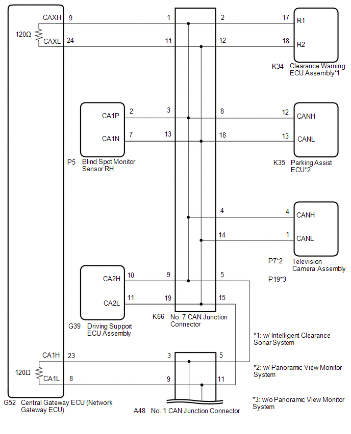
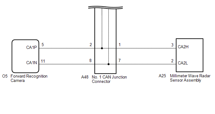
WIRING DIAGRAM
CAUTION / NOTICE / HINT
CAUTION:
When performing the confirmation driving pattern, obey all speed limits and traffic laws.
NOTICE:
Click here 
Click here
DTC check procedure: Turn the engine switch on (IG) and wait for 1 minute or more. Then operate the suspected malfunctioning system and drive the vehicle at 60 km/h (37 mph) or more for 5 minutes or more.
Click here
HINT:
PROCEDURE
|
1. | CHECK FOR SHORT TO +B IN CAN BUS LINE (NO. 1 CAN JUNCTION CONNECTOR) |
(a) Disconnect the cable from the negative (-) battery terminal.
(b) Disconnect the A48 No. 1 CAN junction connector.
(c) Measure the resistance according to the value(s) in the table below.
|
*1 | DLC3 |
- | - |
|
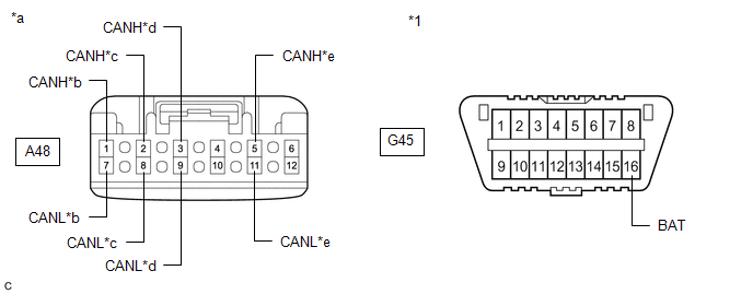
*a | Front view of wire harness connector (to No. 1 CAN Junction Connector) |
*b | to Millimeter Wave Radar Sensor Assembly |
|
*c | to Forward Recognition Camera |
*d | to Central Gateway ECU (Network Gateway ECU) |
|
*e | to No. 7 CAN Junction Connector |
- | - |
Standard Resistance:
|
Tester Connection | Condition |
Specified Condition | Connected to |
|---|---|---|---|
|
A48-1 (CANH) - G45-16 (BAT) |
Cable disconnected from negative (-) battery terminal |
6 kΩ or higher |
Millimeter wave radar sensor assembly |
|
A48-7 (CANL) - G45-16 (BAT) | |||
|
A48-2 (CANH) - G45-16 (BAT) |
Cable disconnected from negative (-) battery terminal |
6 kΩ or higher |
Forward recognition camera |
|
A48-8 (CANL) - G45-16 (BAT) | |||
|
A48-3 (CANH) - G45-16 (BAT) |
Cable disconnected from negative (-) battery terminal |
6 kΩ or higher |
Central gateway ECU (network gateway ECU) |
|
A48-9 (CANL) - G45-16 (BAT) | |||
|
A48-5 (CANH) - G45-16 (BAT) |
Cable disconnected from negative (-) battery terminal |
6 kΩ or higher |
No. 7 CAN junction connector |
|
A48-11 (CANL) - G45-16 (BAT) |
|
Result | Proceed to |
|---|---|
|
OK | A |
|
NG (Line to central gateway ECU (network gateway ECU)) |
B |
| NG (Line to No. 7 CAN junction connector) |
C |
| NG (Line to ECU or sensor) |
D |
| A |
 | REPLACE NO. 1 CAN JUNCTION CONNECTOR |
| C |
| GO TO STEP 3 |
| D |
| GO TO STEP 5 |
|
| 2. |
CHECK FOR SHORT TO +B IN CAN BUS LINE (NO. 1 CAN JUNCTION CONNECTOR - CENTRAL GATEWAY ECU (NETWORK GATEWAY ECU)) |
(a) Disconnect the G52 central gateway ECU (network gateway ECU) connector.
(b) Measure the resistance according to the value(s) in the table below.
|
*1 | DLC3 |
- | - |
|
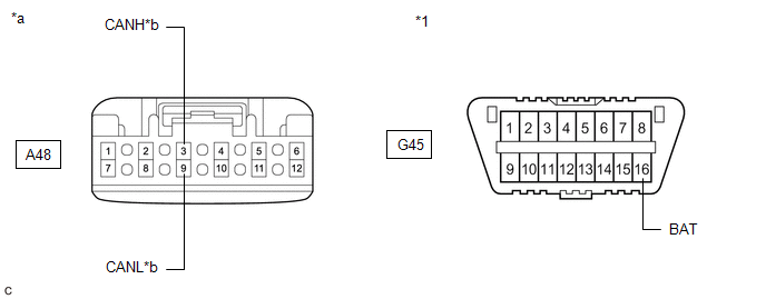
*a | Front view of wire harness connector (to No. 1 CAN Junction Connector) |
*b | to Central Gateway ECU (Network Gateway ECU) |
Standard Resistance:
|
Tester Connection | Condition |
Specified Condition |
|---|---|---|
|
A48-3 (CANH) - G45-16 (BAT) |
Cable disconnected from negative (-) battery terminal |
6 kΩ or higher |
|
A48-9 (CANL) - G45-16 (BAT) |
| OK | | REPLACE CENTRAL GATEWAY ECU (NETWORK GATEWAY ECU) |
| NG | | REPAIR OR REPLACE CAN MAIN BUS LINE OR CONNECTOR (NO. 1 CAN JUNCTION CONNECTOR - CENTRAL GATEWAY ECU (NETWORK GATEWAY ECU)) |
| 3. |
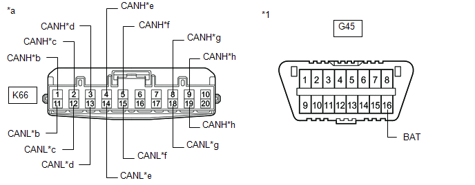
CHECK FOR SHORT TO +B IN CAN BUS LINE (NO. 7 CAN JUNCTION CONNECTOR) |
(a) Disconnect the K66 No. 7 CAN junction connector.
(b) Measure the resistance according to the value(s) in the table below.
|
*1 | DLC3 |
- | - |
|
*a | Front view of wire harness connector (to No. 7 CAN Junction Connector) |
*b | to Central Gateway ECU (Network Gateway ECU) |
|
*c | to Clearance Warning ECU Assembly (w/ Intelligent Clearance Sonar System) |
*d | to Blind Spot Monitor Sensor RH |
|
*e | to Television Camera Assembly |
*f | to No. 1 CAN Junction Connector |
|
*g | to Parking Assist ECU (w/ Panoramic View Monitor System) |
*h | to Driving Support ECU Assembly |
Standard Resistance:
|
Tester Connection | Condition |
Specified Condition | Connected to |
|---|---|---|---|
|
K66-1 (CANH) - G45-16 (BAT) |
Cable disconnected from negative (-) battery terminal |
6 kΩ or higher |
Central gateway ECU (network gateway ECU) |
|
K66-11 (CANL) - G45-16 (BAT) | |||
|
K66-2 (CANH) - G45-16 (BAT) |
Cable disconnected from negative (-) battery terminal |
6 kΩ or higher |
Clearance warning ECU assembly*1 |
|
K66-12 (CANL) - G45-16 (BAT) | |||
|
K66-3 (CANH) - G45-16 (BAT) |
Cable disconnected from negative (-) battery terminal |
6 kΩ or higher |
Blind spot monitor sensor RH |
|
K66-13 (CANL) - G45-16 (BAT) | |||
|
K66-4 (CANH) - G45-16 (BAT) |
Cable disconnected from negative (-) battery terminal |
6 kΩ or higher |
Television camera assembly |
|
K66-14 (CANL) - G45-16 (BAT) | |||
|
K66-5 (CANH) - G45-16 (BAT) |
Cable disconnected from negative (-) battery terminal |
6 kΩ or higher |
No. 1 CAN junction connector |
|
K66-15 (CANL) - G45-16 (BAT) | |||
|
K66-8 (CANH) - G45-16 (BAT) |
Cable disconnected from negative (-) battery terminal |
6 kΩ or higher |
Parking assist ECU*2 |
|
K66-18 (CANL) - G45-16 (BAT) | |||
|
K66-9 (CANH) - G45-16 (BAT) |
Cable disconnected from negative (-) battery terminal |
6 kΩ or higher |
Driving support ECU assembly |
|
K66-19 (CANL) - G45-16 (BAT) |
|
Result | Proceed to |
|---|---|
|
OK | A |
|
NG (Line to central gateway ECU (network gateway ECU)) |
B |
| NG (Line to No. 1 CAN junction connector) |
C |
| NG (Line to ECU or sensor) |
D |
| A |
| REPLACE NO. 7 CAN JUNCTION CONNECTOR |
| C |
| REPAIR OR REPLACE CAN MAIN BUS LINE OR CONNECTOR (NO. 7 CAN JUNCTION CONNECTOR - NO. 1 CAN JUNCTION CONNECTOR) |
| D |
| GO TO STEP 5 |
|
| 4. |
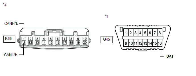
CHECK FOR SHORT TO +B IN CAN BUS LINE (NO. 7 CAN JUNCTION CONNECTOR - CENTRAL GATEWAY ECU (NETWORK GATEWAY ECU)) |
(a) Disconnect the G52 central gateway ECU (network gateway ECU) connector.
(b) Measure the resistance according to the value(s) in the table below.
|
*1 | DLC3 |
- | - |
|
*a | Front view of wire harness connector (to No. 7 CAN Junction Connector) |
*b | to Central Gateway ECU (Network Gateway ECU) |
Standard Resistance:
|
Tester Connection | Condition |
Specified Condition |
|---|---|---|
|
K66-1 (CANH) - G45-16 (BAT) |
Cable disconnected from negative (-) battery terminal |
6 kΩ or higher |
|
K66-11 (CANL) - G45-16 (BAT) |
| OK | | REPLACE CENTRAL GATEWAY ECU (NETWORK GATEWAY ECU) |
| NG | | REPAIR OR REPLACE CAN MAIN BUS LINE OR CONNECTOR (NO. 7 CAN JUNCTION CONNECTOR - CENTRAL GATEWAY ECU (NETWORK GATEWAY ECU)) |
| 5. |
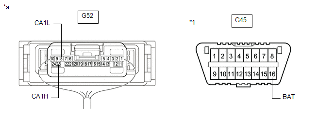
CHECK FOR SHORT TO +B IN CAN BUS LINE (ECU OR SENSOR) |
(a) Reconnect all wire harness connectors.
(b) Disconnect the connector that includes terminals CANH and CANL from the ECU or sensor to which the bus line shorted to +B is connected.
Click here
(c) Measure the resistance according to the value(s) in the table below.
|
*1 | DLC3 |
- | - |
|
*a | Component with harness connected (Central Gateway ECU (Network Gateway ECU)) |
- | - |
Standard Resistance:
|
Tester Connection | Condition |
Specified Condition |
|---|---|---|
|
G52-23 (CA1H) - G45-16 (BAT) |
Cable disconnected from negative (-) battery terminal |
6 kΩ or higher |
|
G52-8 (CA1L) - G45-16 (BAT) |
HINT:
| OK | | REPLACE ECU OR SENSOR |
| NG | | REPAIR OR REPLACE HARNESS OR CONNECTOR |
Toyota Avalon (XX50) 2019-2022 Service & Repair Manual > Sfi System: Radiator Coolant Temperature Sensor Signal Compare Failure (P00B162). A/F (O2) Sensor Correlation Bank 1 Sensor 1/Bank 1 Sensor 2 Signal Compare Failure (P00D562). Active Grille Air Shutter "A" Actuat
Radiator Coolant Temperature Sensor Signal Compare Failure (P00B162) DESCRIPTION This engine uses a No. 2 engine coolant temperature sensor and an intake air temperature sensor to detect temperatures related to engine operation. A thermistor, whose resistance value varies according to the temperatur ...


