Toyota Avalon (XX50): Active Noise Control ECU Communication Stop Mode. Air Conditioning Amplifier Communication Stop Mode. ECU Malfunction (B1003)
Active Noise Control ECU Communication Stop Mode
DESCRIPTION
|
Detection Item | Symptom |
Trouble Area |
| Active Noise Control ECU Communication Stop Mode |
Any of the following conditions are met:
- Communication stop for "Active Noise Control" is indicated on the "Communication Bus Check" screen of the Techstream.
Click here 
- Communication stop history for "Active Noise Control" is indicated on
the "Communication Bus Check (Detail)" screen of the Techstream. (The
Lost Communication Time value for "Active Noise Control" is 6 or more.)
Click here
- Communication system DTCs (DTCs that start with U) that correspond to
"Active Noise Control ECU Communication Stop Mode" in "DTC Combination
Table" are output.
Click here
|
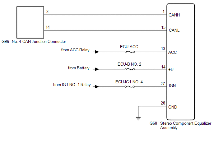
- Stereo component equalizer assembly branch line or connector
- Power source circuit of stereo component equalizer assembly
- Stereo component equalizer assembly ground circuit
- Stereo component equalizer assembly
|
WIRING DIAGRAM
CAUTION / NOTICE / HINT
CAUTION:
When performing the confirmation driving pattern, obey all speed limits and traffic laws.
NOTICE:
HINT:
- Before disconnecting related connectors for inspection, push in on each
connector body to check that the connector is not loose or disconnected.
- When a connector is disconnected, check that the terminals and connector body are not cracked, deformed or corroded.
PROCEDURE
|
1. | CHECK FOR OPEN IN CAN BUS LINES (STEREO COMPONENT EQUALIZER ASSEMBLY BRANCH LINE) |
(a) Disconnect the cable from the negative (-) battery terminal.
(b) Disconnect the G68 stereo component equalizer assembly connector.
| (c) Measure the resistance according to the value(s) in the table below.
Standard Resistance: |
Tester Connection | Condition |
Specified Condition | |
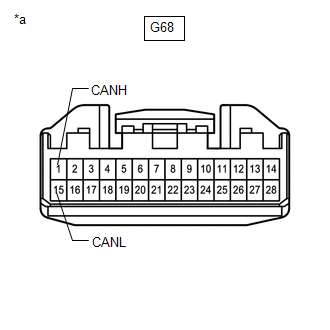
G68-1 (CANH) - G68-15 (CANL) |
Cable disconnected from negative (-) battery terminal |
54 to 69 Ω | |
 |
|
*a | Front view of wire harness connector
(to Stereo Component Equalizer Assembly) | | |
| NG |
 | REPAIR OR REPLACE CAN BRANCH LINES OR CONNECTOR (STEREO COMPONENT EQUALIZER ASSEMBLY) |
|
OK |
 | |
| 2. |
CHECK HARNESS AND CONNECTOR (POWER SOURCE CIRCUIT) |
| (a) Measure the resistance according to the value(s) in the table below.
Standard Resistance: |
Tester Connection | Condition |
Specified Condition | |
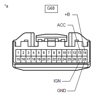
G68-28 (GND) - Body ground |
Cable disconnected from negative (-) battery terminal |
Below 1 Ω | |
 |
|
*a | Front view of wire harness connector
(to Stereo Component Equalizer Assembly) | | |
(b) Reconnect the cable to the negative (-) battery terminal.
(c) Measure the voltage according to the value(s) in the table below.
Standard Voltage:
|
Tester Connection | Condition |
Specified Condition |
|
G68-13 (ACC) - Body ground |
Engine switch on (ACC) |
11 to 14 V |
|
G68-14 (+B) - Body ground |
Always | 11 to 14 V |
|
G68-27 (IGN) - Body ground |
Engine switch on (IG) |
11 to 14 V |
| OK |
| REPLACE STEREO COMPONENT EQUALIZER ASSEMBLY |
| NG |
| REPAIR OR REPLACE HARNESS OR CONNECTOR (POWER SOURCE CIRCUIT) |
Air Conditioning Amplifier Communication Stop Mode
DESCRIPTION
|
Detection Item | Symptom |
Trouble Area |
| Air Conditioning Amplifier Communication Stop Mode |
Any of the following conditions are met:
- Communication stop for "Air Conditioning Amplifier" is indicated on the "Communication Bus Check" screen of the Techstream.
Click here 
- Communication stop history for "Air Conditioning Amplifier" is indicated
on the "Communication Bus Check (Detail)" screen of the Techstream.
(The Lost Communication Time value for "Air Conditioning Amplifier" is 6
or more.)
Click here
- Communication system DTCs (DTCs that start with U) that correspond to
"Air Conditioning Amplifier Communication Stop Mode" in "DTC Combination
Table" are output.
Click here
|
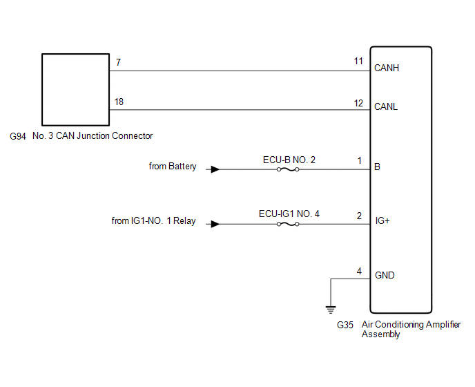
- Air conditioning amplifier assembly branch line or connector
- Power source circuit of air conditioning amplifier assembly
- Air conditioning amplifier assembly ground circuit
- Air conditioning amplifier assembly
|
WIRING DIAGRAM
CAUTION / NOTICE / HINT
CAUTION:
When performing the confirmation driving pattern, obey all speed limits and traffic laws.
NOTICE:
HINT:
- Before disconnecting related connectors for inspection, push in on each
connector body to check that the connector is not loose or disconnected.
- When a connector is disconnected, check that the terminals and connector body are not cracked, deformed or corroded.
PROCEDURE
|
1. | CHECK FOR OPEN IN CAN BUS LINES (AIR CONDITIONING AMPLIFIER ASSEMBLY BRANCH LINE) |
(a) Disconnect the cable from the negative (-) battery terminal.
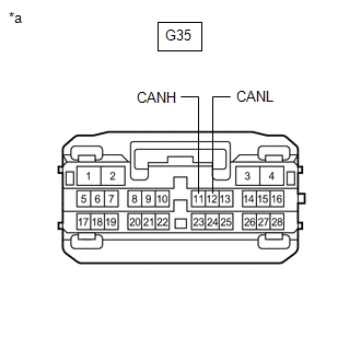
(b) Disconnect the G35 air conditioning amplifier assembly connector.
| (c) Measure the resistance according to the value(s) in the table below.
Standard Resistance: |
Tester Connection | Condition |
Specified Condition | |
G35-11 (CANH) - G35-12 (CANL) |
Cable disconnected from negative (-) battery terminal |
54 to 69 Ω | |
 |
|
*a | Front view of wire harness connector
(to Air Conditioning Amplifier Assembly) | | |
| NG |
 | REPAIR OR REPLACE CAN BRANCH LINES OR CONNECTOR (AIR CONDITIONING AMPLIFIER ASSEMBLY) |
|
OK |
 | |
| 2. |
CHECK HARNESS AND CONNECTOR (POWER SOURCE CIRCUIT) |
| (a) Measure the resistance according to the value(s) in the table below.
Standard Resistance: |
Tester Connection | Condition |
Specified Condition | |
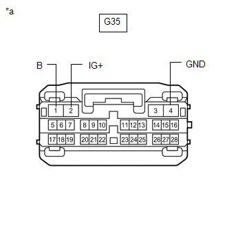
G35-4 (GND) - Body ground |
Cable disconnected from negative (-) battery terminal |
Below 1 Ω | |
 |
|
*a | Front view of wire harness connector
(to Air Conditioning Amplifier Assembly) | | |
(b) Reconnect the cable to the negative (-) battery terminal.
(c) Measure the voltage according to the value(s) in the table below.
Standard Voltage:
|
Tester Connection | Condition |
Specified Condition |
|
G35-1 (B) - Body ground |
Always | 11 to 14 V |
|
G35-2 (IG+) - Body ground |
Engine switch on (IG) |
11 to 14 V |
| OK |
| REPLACE AIR CONDITIONING AMPLIFIER ASSEMBLY |
| NG |
| REPAIR OR REPLACE HARNESS OR CONNECTOR (POWER SOURCE CIRCUIT) |
ECU Malfunction (B1003)
DESCRIPTION
|
DTC No. | Detection Item |
DTC Detection Condition | Trouble Area |
Note |
| B1003 |
ECU Malfunction | A malfunction in the non-volatile storage of the central gateway ECU (network gateway ECU) is detected. |
Central gateway ECU (network gateway ECU) |
- |
PROCEDURE
(a) Connect the Techstream to the DLC3.
(b) Turn the engine switch on (IG).
(c) Turn the Techstream on.
(d) Enter the following menus: Body Electrical / Central Gateway / Trouble Codes.
Body Electrical > Central Gateway > Trouble Codes
|
Result | Proceed to |
|
DTC B1003 is not output from the central gateway ECU (network gateway ECU) |
A |
| DTC B1003 is output from the central gateway ECU (network gateway ECU) |
B |
| A |
 | USE SIMULATION METHOD TO CHECK |
| B |
| REPLACE CENTRAL GATEWAY ECU (NETWORK GATEWAY ECU) |


