Components
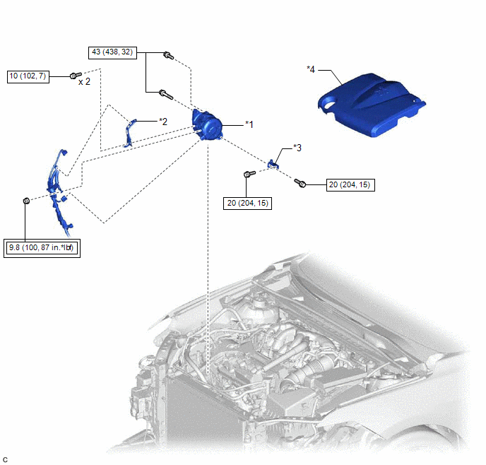
COMPONENTS
ILLUSTRATION
|
*1 | GENERATOR ASSEMBLY |
*2 | WIRE HARNESS CLAMP BRACKET |
|
*3 | GENERATOR ASSEMBLY BRACKET |
*4 | V-BANK COVER SUB-ASSEMBLY |
 |
Tightening torque for "Major areas involving basic vehicle performance such as moving/turning/stopping": N*m (kgf*cm, ft.*lbf) |
 |
N*m (kgf*cm, ft.*lbf): Specified torque |
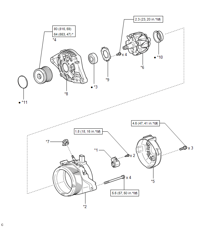
ILLUSTRATION
|
*1 | GENERATOR BRUSH HOLDER ASSEMBLY |
*2 | GENERATOR COIL ASSEMBLY |
|
*3 | GENERATOR DRIVE END FRAME BEARING |
*4 | GENERATOR PULLEY WITH CLUTCH |
|
*5 | GENERATOR REAR END COVER |
*6 | GENERATOR ROTOR ASSEMBLY |
|
*7 | GENERATOR TERMINAL INSULATOR |
*8 | GENERATOR DRIVE END FRAME |
|
*9 | RETAINER PLATE |
*10 | BEARING COVER PACKING |
|
*11 | GENERATOR PULLEY CAP |
- | - |
 |
N*m (kgf*cm, ft.*lbf) : Specified torque |
* | For use with SST |
|
â—Ź | Non-reusable part |
- | - |
Disassembly
DISASSEMBLY
PROCEDURE
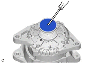
1. REMOVE GENERATOR PULLEY CAP
| (a) Using a screwdriver, remove the generator pulley cap from the generator pulley with clutch.
NOTICE: Do not reuse the generator pulley cap. | |
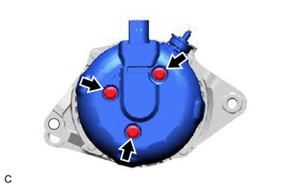
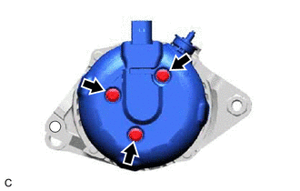
2. REMOVE GENERATOR REAR END COVER
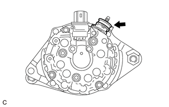
| (a) Remove the 3 bolts and generator rear end cover from the generator coil assembly. |
|
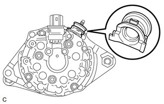
3. REMOVE GENERATOR TERMINAL INSULATOR
| (a) Remove the generator terminal insulator from the generator coil assembly. |
|
4. REMOVE GENERATOR BRUSH HOLDER ASSEMBLY
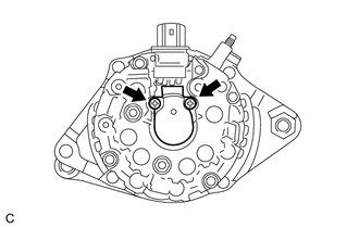
| (a) Remove the 2 screws and generator brush holder assembly from the generator coil assembly. |
|
5. REMOVE GENERATOR COIL ASSEMBLY
| (b) Using SST, remove the generator coil assembly from the generator rotor assembly.
SST: 09950-40011 09951-04020 09952-04010 09953-04020
09954-04010 09955-04071 09957-04010 09958-04011 |
|
| (c) Remove the bearing cover packing. NOTICE: If the bearing cover packing breaks, remove the broken pieces completely.
HINT: The bearing cover packing may be installed on the generator rotor assembly. |
|
6. REMOVE GENERATOR PULLEY WITH CLUTCH
(a) Secure the generator drive end frame in a vise between aluminum plates.
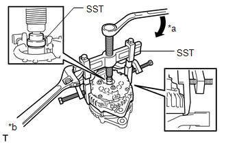
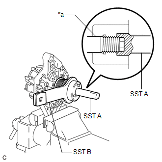
| (b) Install SST (A) and (B) to the generator pulley with clutch as shown in the illustration.
SST: 09820-63021 NOTICE: Securely attach SST to the generator pulley with clutch and rotor shaft. |
|
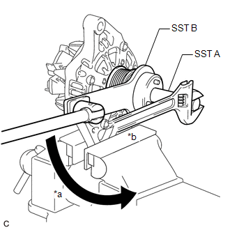
| (c) Loosen the generator pulley with clutch by turning SST (B) as shown in the illustration.
NOTICE:
- Check that the generator drive end frame is secured in the vise tightly.
- Hold SST (A) tightly during the operation.
| |
(d) Remove SST from the generator pulley with clutch.
(e) Remove the generator pulley with clutch from the rotor shaft.
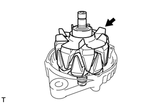
7. REMOVE GENERATOR ROTOR ASSEMBLY
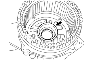
| (a) Remove the generator rotor assembly from the generator drive end frame. |
|
8. INSPECT GENERATOR DRIVE END FRAME BEARING
Click here

9. REMOVE GENERATOR DRIVE END FRAME BEARING
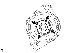
| (a) Remove the 4 screws and retainer plate from the generator drive end frame. |
|
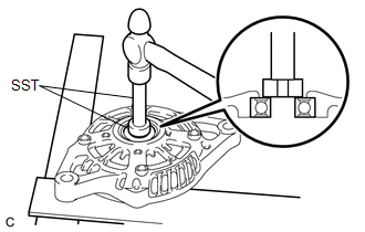
| (b) Using SST and a hammer, tap out the generator drive end frame bearing from the generator drive end frame.
SST: 09950-60010 09951-00250 SST: 09950-70010 09951-07100 |
|
Inspection
INSPECTION
PROCEDURE
1. INSPECT GENERATOR PULLEY WITH CLUTCH
(a)
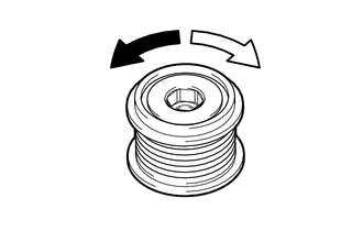
Hold the center of the generator pulley with clutch, and confirm that
the outer ring turns counterclockwise and does not turn clockwise.
OK:
The outer ring turns counterclockwise and does not turn clockwise.
If the result is not as specified, replace the generator pulley with clutch.
 |
Free |
 |
Lock |
2. INSPECT GENERATOR BRUSH HOLDER ASSEMBLY
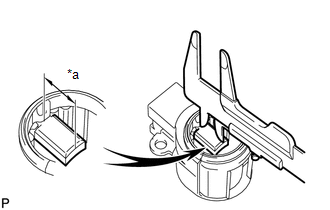
| (a) Using a vernier caliper, measure the length of the exposed brushes.
Standard Exposed Brush Length: 9.5 to 11.5 mm (0.374 to 0.453 in.)
Minimum Exposed Brush Length: 4.5 mm (0.177 in.) If the brush length is less than the minimum, replace the generator brush holder assembly. |
|
3. INSPECT GENERATOR ROTOR ASSEMBLY
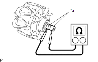
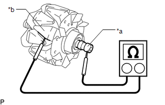
| (a) Check the generator rotor assembly for an open circuit. (1) Measure the resistance according to the value(s) in the table below.
Standard Resistance: |
Tester Connection | Condition |
Specified Condition | |
Slip ring - Slip ring |
20°C (68°F) | 1.8 to 2.2 Ω (for 100A Type) | |
1.6 to 2.0 Ω (for 130A Type) | If the result is not as specified, replace the generator rotor assembly. |
|
| (b) Check the generator rotor assembly for a short to ground.
(1) Measure the resistance according to the value(s) in the table below.
Standard Resistance: |
Tester Connection | Condition |
Specified Condition | |
Slip ring - Rotor |
Always | 1 MΩ or higher |
If the result is not as specified, replace the generator rotor assembly. |
|
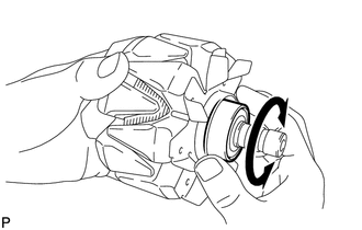
| (c) Check that the generator rotor bearing is not rough or worn and that it rotates smoothly.
If the generator rotor bearing is rough or worn, or does not rotate smoothly, replace the generator rotor assembly. |
|
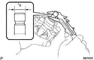
| (d) Check the slip ring. (1) Check that the slip rings are not rough or scored.
If the slip rings are rough or scored, replace the generator rotor assembly.
(2) Using a vernier caliper, measure the slip ring diameter. Standard Diameter:
14.2 to 14.8 mm (0.559 to 0.583 in.) Minimum Diameter: 14.0 mm (0.551 in.)
If the diameter is less than the minimum, replace the generator rotor assembly. |
|
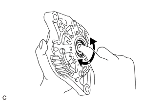
4. INSPECT GENERATOR DRIVE END FRAME BEARING
| (a) Check that the generator drive end frame bearing is not rough or worn and that it rotates smoothly.
If
the generator drive end frame bearing is rough or worn, or does not
rotate smoothly, replace the generator drive end frame bearing. | |
Installation
INSTALLATION
PROCEDURE
1. INSTALL GENERATOR ASSEMBLY
(a) Install the generator assembly with the 2 bolts.
Torque:
43 N·m {438 kgf·cm, 32 ft·lbf}
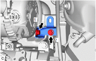
| (b) Install the generator assembly bracket with the 2 bolts in the order shown in the illustration.
Torque: 20 N·m {204 kgf·cm, 15 ft·lbf} | |
(c) Install the wire harness clamp bracket with the 2 bolts.
Torque:
10 N·m {102 kgf·cm, 7 ft·lbf}
(d) Engage the 3 wire harness clamps.
(e) Connect the camshaft timing oil control solenoid assembly connector.
(f) Connect the compressor assembly with magnetic clutch connector.
(g) Connect the generator assembly connector.
(h) Connect the wire harness to terminal B with the nut.
Torque:
9.8 N·m {100 kgf·cm, 87 in·lbf}
(i) Close the terminal cap.
2. INSTALL V-RIBBED BELT
Click here 
3. INSTALL V-BANK COVER SUB-ASSEMBLY
Click here 
4. INSTALL RADIATOR ASSEMBLY
Click here 
5. CONNECT CABLE TO NEGATIVE BATTERY TERMINAL
NOTICE:
When disconnecting the cable, some systems need to be initialized after the cable is reconnected.
Click here 
Reassembly
REASSEMBLY
PROCEDURE
1. INSTALL GENERATOR DRIVE END FRAME BEARING
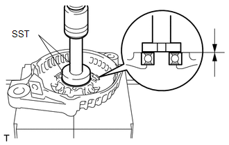
| (a) Using SST and a press, install a new generator drive end frame bearing to the generator drive end frame.
SST: 09950-60010 09951-00470 SST: 09950-70010 09951-07100 |
|
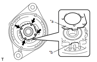
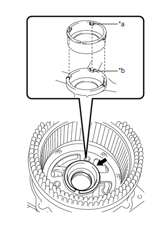
| (b) Fit the tabs of the retainer plate into the cutouts of the generator drive end frame to install the retainer plate. |
|
(c) Install the 4 screws.
Torque:
2.3 N·m {23 kgf·cm, 20 in·lbf}
2. INSTALL GENERATOR ROTOR ASSEMBLY
(a) Place the generator drive end frame on the generator pulley with clutch.
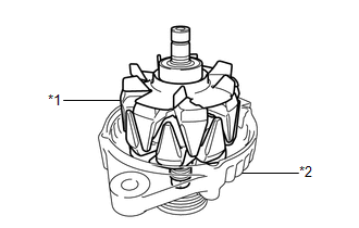
| (b) Install the generator rotor assembly to the generator drive end frame. |
 |
|
*1 | Generator Rotor Assembly | |
*2 | Generator Drive End Frame | | |
3. INSTALL GENERATOR PULLEY WITH CLUTCH
(a) Temporarily install the generator pulley with clutch to the rotor shaft.
(b) Secure the generator drive end frame in a vise between aluminum plates.
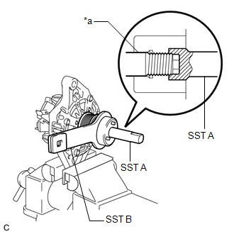
| (c) Place the rotor shaft end into SST (A). SST: 09820-63021 |
|
(d) Fit SST (B) to the generator pulley with clutch.
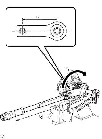
| (e) Tighten the generator pulley with clutch by turning SST (B) as shown in the illustration.
Torque: Specified tightening torque : 80 N·m {816 kgf·cm, 59 ft·lbf}
HINT:
- Calculate the torque wrench reading when changing the fulcrum length of the torque wrench.
Click here 
- When using SST (fulcrum length of 100 mm (3.94 in.)) + torque wrench
(fulcrum length of 400 mm (1.312 ft.)): 64 N*m (653 kgf*cm, 47 ft.*lbf)
|
 |
|
*a | Hold | |
*b | Turn | |
*c | Length of SST 100 mm (3.94 in.) | |
*d | Length of Torque Wrench 400 mm (1.31 ft.) | | |
(f) Remove SST (A) and (B) from the generator pulley with clutch.
(g) Check that the generator pulley with clutch rotates smoothly.
(h) Remove the generator drive end frame from the vise.
4. INSTALL GENERATOR COIL ASSEMBLY
| (a) Install a new bearing cover packing. NOTICE: Align the protrusions of the bearing cover packing with the grooves of the generator coil assembly when installing. |
|
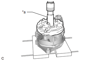
| (b) Using a 21 mm socket wrench and press, slowly press the generator coil assembly to install it. |
|
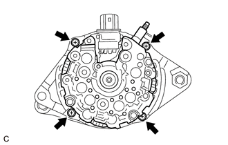
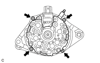
| (c) Install the 4 bolts. Torque: 5.6 N·m {57 kgf·cm, 50 in·lbf} |
|
5. INSTALL GENERATOR BRUSH HOLDER ASSEMBLY
| (a)
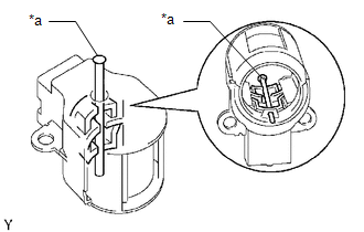
While pushing the 2 brushes into the generator brush holder assembly,
insert a 1.0 mm (0.0394 in.) pin into the generator brush holder
assembly hole. | |
(b) Install the generator brush holder assembly to the generator coil assembly with the 2 screws.
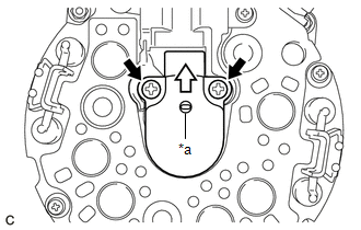
|
*a | Pin (1.0 mm) |
 |
Pull out |
Torque:
1.8 N·m {18 kgf·cm, 16 in·lbf}
(c) Pull out the pin from the generator brush holder assembly hole.
6. INSTALL GENERATOR TERMINAL INSULATOR
| (a) Install the generator terminal insulator to the generator coil assembly.
NOTICE: Be sure to install the generator terminal insulator in the correct direction. |
|
7. INSTALL GENERATOR REAR END COVER
| (a) Install the generator rear end cover to the generator coil assembly with the 3 bolts.
Torque: 4.6 N·m {47 kgf·cm, 41 in·lbf} | |
8. INSTALL GENERATOR PULLEY CAP
(a) Install a new generator pulley cap to the generator pulley with clutch.
Removal
REMOVAL
CAUTION / NOTICE / HINT
The
necessary procedures (adjustment, calibration, initialization or
registration) that must be performed after parts are removed and
installed, or replaced generator assembly removal/installation are shown
below.
Necessary Procedures After Parts Removed/Installed/Replaced |
Replaced Part or Performed Procedure |
Necessary Procedure | Effect/Inoperative Function when Necessary Procedure not Performed |
Link |
|
*: When performing learning using the Techstream.
Click here  |
|
Battery terminal is disconnected/reconnected |
Perform steering sensor zero point calibration |
Lane departure alert system (w/ Steering Control) |
 |
|
Pre-collision system |
|
Intelligent clearance sonar system* |
|
Lighting System (for Gasoline Model with Cornering Light) |
|
Memorize steering angle neutral point |
Parking assist monitor system |
 |
|
Panoramic view monitor system |
 |
|
Front bumper assembly (w/ Panoramic view monitor system) |
Front television camera view adjustment |
Panoramic view monitor system |
 for Initialization for Initialization
 for Calibration for Calibration |
|
Front bumper assembly (w/ Intuitive Parking Assist System) |
- Measure ultrasonic sensor detection angle
- Ultrasonic sensor detection angle registration
|
- Intelligent clearance sonar system
- Intuitive parking assist system
|
 |
PROCEDURE
1. PRECAUTION
NOTICE:
After
turning the engine switch off, waiting time may be required before
disconnecting the cable from the negative (-) battery terminal.
Therefore, make sure to read the disconnecting the cable from the
negative (-) battery terminal notices before proceeding with work.
Click here

2. DISCONNECT CABLE FROM NEGATIVE BATTERY TERMINAL
NOTICE:
When disconnecting the cable, some systems need to be initialized after the cable is reconnected.
Click here 
3. REMOVE RADIATOR ASSEMBLY
Click here 
4. REMOVE V-BANK COVER SUB-ASSEMBLY
Click here 
5. REMOVE V-RIBBED BELT
Click here 
6. REMOVE GENERATOR ASSEMBLY
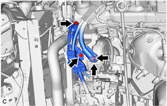
| (a) Open the terminal cap. | |
(b) Remove the nut and disconnect the wire harness from terminal B.
(c) Remove the 2 bolts.
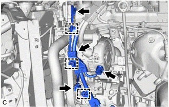
| (d) Disconnect the generator assembly connector. | |
(e) Disconnect the compressor assembly with magnetic clutch connector.
(f) Disconnect the camshaft timing oil control solenoid assembly connector.
(g) Disengage the 3 wire harness clamps and remove the wire harness clamp bracket.
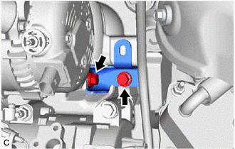
| (h) Remove the 2 bolts and generator assembly bracket. |
|
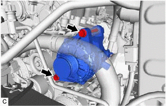
| (i) Remove the 2 bolts and generator assembly. | |














 for Initialization
 for Calibration


